Detailed Notes for Resonance | Network Theory (Electric Circuits) - Electrical Engineering (EE) PDF Download

Introduction
In Network Theory, resonance is a fundamental phenomenon that occurs in electrical circuits containing reactive elements like inductors (L) and capacitors (C) when driven by an AC source. It is the condition where the circuit's reactive components balance each other, leading to unique electrical behaviors. Resonance is critical in understanding impedance, power transfer, and damping, and it finds wide applications in filters, tuners, and oscillators. For GATE aspirants, mastering resonance is essential as it connects circuit analysis with practical engineering applications and maximum power transfer principles.Resonance Conditions
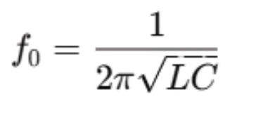
Resonance occurs in an AC circuit when the imaginary part of the total impedance becomes zero, i.e., the inductive reactance (X_L = ωL) equals the capacitive reactance (X_C = 1/ωC). This balance defines the resonant frequency (f₀), given by:
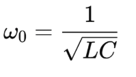
 or in terms of angular frequency:
There are two main types of resonance in circuits:
- Series Resonance: Occurs in a series RLC circuit where the impedance is minimum at resonance.
- Parallel Resonance: Occurs in a parallel RLC circuit where the impedance is maximum at resonance.
The condition for resonance depends on the circuit configuration, but the core idea is the cancellation of inductive and capacitive effects at ω₀.
Impedance Behavior at Resonance
Series RLC Circuit:
- At resonance, X_L = X_C, so the total impedance reduces to just the resistance (Z = R).
- This is the minimum impedance condition, leading to maximum current (I = V/R).
- The phase angle between voltage and current is zero (purely resistive behavior).
Parallel RLC Circuit:
- At resonance, the admittance (Y = 1/Z) becomes minimum because the inductive susceptance (B_L = 1/ωL) cancels the capacitive susceptance (B_C = ωC).
- The impedance is maximum (Z = R_p, where R_p is the equivalent parallel resistance), and the current drawn from the source is minimum.
- The phase angle is again zero.
The impedance behavior dictates how the circuit responds to the AC source, making resonance a key design parameter.
Power at Resonance
Power in an AC circuit is given by P=VIcosϕ, where cosϕ is the power factor.Series Resonance:
- Since Z = R and ϕ=0, the power factor is 1 (maximum).
- All the power supplied is dissipated in the resistor (P = I²R), and no reactive power is stored.
Parallel Resonance:
- The power factor is also 1 at resonance, but the current through the source is minimized due to high impedance.
- Energy oscillates between the inductor and capacitor, with minimal net power drawn from the source.
Resonance thus optimizes power delivery or minimizes power loss, depending on the circuit type.
Damping Effects at Resonance
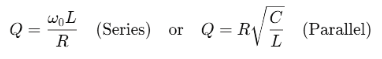
Damping refers to the decay of oscillations in a resonant circuit, influenced by the resistance (R). It is quantified by the quality factor (Q):
Low Damping (High Q):
- Small R in series or large R in parallel leads to sharp resonance peaks and sustained oscillations.
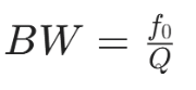
- Bandwidth (BW) is narrow:
High Damping (Low Q):
- Large R in series or small R in parallel broadens the resonance curve, reducing selectivity.
- Oscillations decay quickly.
Damping affects the sharpness of resonance and is crucial for applications requiring specific frequency responses.
Applications of Resonance
Resonance is widely used in electrical engineering:
- Filters:
- Band-pass Filters: Series RLC circuits allow a narrow band of frequencies near f₀ to pass (high Q).
- Band-stop Filters: Parallel RLC circuits reject frequencies near f₀.
- Tuners:
- In radios, LC circuits are tuned to resonate at the desired station frequency, selecting it from the spectrum.
- Oscillators:
- LC tank circuits in oscillators (e.g., Hartley, Colpitts) use resonance to generate sustained AC signals at f₀.
- Other Uses:
- Impedance matching, signal amplification, and frequency stabilization in communication systems.
These applications exploit resonance’s ability to selectively enhance or suppress frequencies.
Maximum Power Transfer at Resonance
The Maximum Power Transfer Theorem states that maximum power is delivered to a load when the source impedance matches the load impedance (conjugate match for complex impedances). At resonance:
Series Circuit:
- Impedance is purely resistive (Z = R), and maximum power is transferred to the resistor when the source resistance equals R.
- Power delivered:
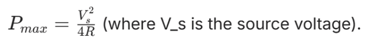
Parallel Circuit:
- At resonance, the load appears resistive, and power transfer is maximized when the source resistance equals the equivalent parallel resistance.
Resonance ensures the reactive components don’t impede power flow, aligning with the theorem’s conditions for optimal efficiency.
Conclusion
Resonance is a captivating phenomenon that reveals the harmony between inductors and capacitors in electrical circuits. By aligning their reactive effects at a specific frequency, it transforms impedance—minimizing it in series circuits or maximizing it in parallel ones—while optimizing power flow and shaping dynamic responses through damping. The interplay of energy storage and dissipation, captured by the quality factor, defines how sharply or broadly a circuit resonates, influencing its selectivity and behavior. This principle powers practical marvels like filters that isolate frequencies, tuners that pinpoint signals, and oscillators that generate steady waves. Furthermore, resonance enables maximum power transfer by ensuring efficient energy delivery under matched conditions. Together, these aspects highlight resonance as a fundamental concept that bridges theory and application, offering endless possibilities for innovation and exploration in the realm of circuits.
|
76 videos|152 docs|62 tests
|
FAQs on Detailed Notes for Resonance - Network Theory (Electric Circuits) - Electrical Engineering (EE)
| 1. What are the resonance conditions in electrical circuits? |  |
| 2. How does impedance behave at resonance? | |
| 3. What is the significance of power at resonance? | |
| 4. How do damping effects influence resonance? | |
| 5. What are some common applications of resonance? | |


video lectures
,practice quizzes
,Previous Year Questions with Solutions
,ppt
,MCQs
,Objective type Questions
,Exam
,mock tests for examination
,Viva Questions
,Semester Notes
,Sample Paper
,study material
,Extra Questions
,Detailed Notes for Resonance | Network Theory (Electric Circuits) - Electrical Engineering (EE)
,Detailed Notes for Resonance | Network Theory (Electric Circuits) - Electrical Engineering (EE)
,Free
,Important questions
,shortcuts and tricks
,past year papers
,Detailed Notes for Resonance | Network Theory (Electric Circuits) - Electrical Engineering (EE)
,Summary
;


Detailed Notes for Resonance Free PDF Download
Importance of Detailed Notes for Resonance
Detailed Notes for Resonance
Detailed Notes for Resonance Electrical Engineering (EE) Questions
Study Detailed Notes for Resonance on the App
|
© EduRev
|
Education Revolution
|


|


