Power In Three Phase Circuit | Network Theory (Electric Circuits) - Electrical Engineering (EE) PDF Download

Electrical power is distributed in various forms, with single-phase and three-phase systems being the most common. Three-phase power stands out as the preferred choice for generating, transmitting, and distributing electricity due to its efficiency and cost-effectiveness. Unlike single-phase power, which relies on two conductors, three-phase systems use three live conductors, making them ideal for heavy-duty applications.
Single-Phase Power
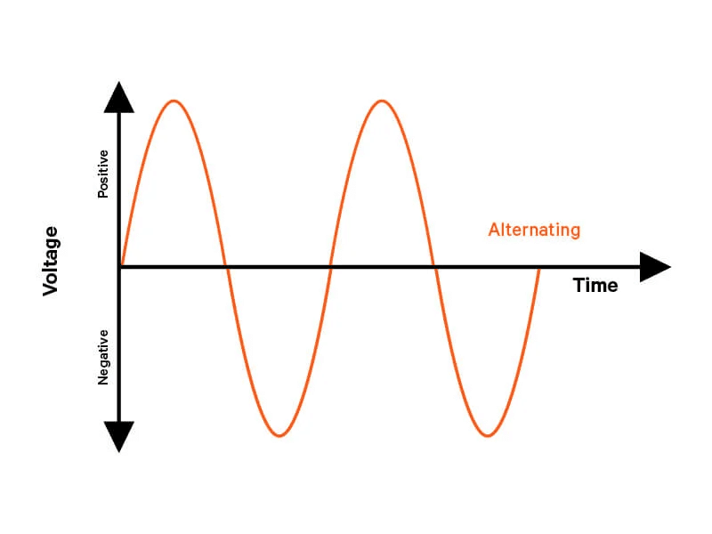
Single-phase alternating current (AC) power operates through two conductors: a phase wire and a neutral wire. The voltage in this system fluctuates sinusoidally, reaching a positive peak during one half-cycle and a negative peak during the next, relative to the neutral wire. The power in a single-phase circuit is calculated as:
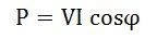
Where:
- V represents the single-phase voltage (Vph),
- I denotes the single-phase current (Iph),
- cos φ is the power factor, indicating the efficiency of power usage.
Key features of single-phase power include:
- It suits small-scale loads, such as those in homes or light commercial setups.
- Voltage and current oscillate with a 180° phase difference.
- It struggles to support large inductive or capacitive loads directly.
3- Phase power
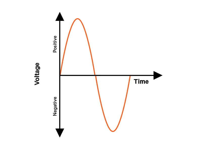
Three-phase power, as the name suggests, uses three separate currents. Each one is spaced out by a third of a cycle, or 120 degrees apart. This is different from single-phase power, where the two currents are always 180 degrees apart—basically opposites.
In a picture like Figure 1, you’d see that when one current is at its highest point, the other two aren’t. For example, when the first current hits its positive peak, the second and third are both at half-strength in the negative direction. Unlike single-phase, where power drops to zero at times, three-phase power never stops delivering. At six points in every cycle, one of the three currents is at its max—either positive or negative.
In real life, this means the total power from all three currents stays steady. There are no ups and downs like with single-phase power. Computers and big machines, like motors in factories, love this because they can pull a constant flow of energy without dealing with the on-and-off nature of single-phase. This makes them run smoother and use less power overall.
Think of it like comparing a one-cylinder engine to a three-cylinder one. In a one-cylinder engine, power comes in bursts—only once every four steps (intake, compression, power, exhaust)—so it feels uneven. A three-cylinder engine, though, spreads the power out across three steps, each 120 degrees apart. That gives you a steady, smooth push instead of a jerky one, making it more efficient. Figure 1
Why We Use Three-Phase Power
As technology gets more advanced, places like data centers and server rooms need a lot more electricity. Today’s computers and networks use way more power than older ones, even though they fit in the same space. This makes it super important to deliver that power in a smart way.
Back in the day, a rack with 10 servers might have needed just 5 kilowatts (kW) of power. Now, the same rack could have tons of servers and use 20 or 30 kW. When you’re dealing with that much power, saving even a little bit can mean big money saved over time.
Wiring is a big deal too. For example, a 15 kW rack using single-phase power at 120 volts needs 125 amps. That means using a thick wire—about a quarter-inch wide—which is hard to work with and costs a lot. But with three-phase power, the same 15 kW can be handled with three smaller wires, each carrying only 42 amps. These wires are tiny—less than a tenth of an inch—making them cheaper and easier to use.
Three-phase power splits the work across three wires, so each one doesn’t have to carry as much. This makes it better at delivering lots of power without needing huge, expensive cables. That’s why it’s perfect for powering today’s high-tech setups.
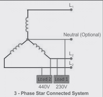
Voltage and Current Values in Three Phase System
A three-phase system involves three equal AC voltages, each separated by a 120° phase difference, ensuring a steady power flow. The voltage between any two phases, known as the line voltage, exceeds the phase voltage, calculated as:
Vline = √3 x Vph
The total power in a balanced three-phase circuit is expressed as:
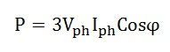
The power in star connections within a three-phase circuit is expressed as:
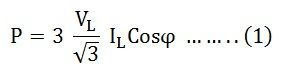
The representation of phase voltage and line voltage in a star connection is as follows:
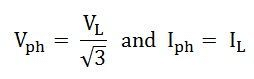
Hence, equation (1) can be expressed as:
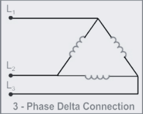
The equation representing the power in delta connections within three-phase circuits is as follows: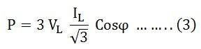
In delta connections, the relationship between phase and line voltage, as well as phase and line current, is represented as: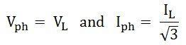
Therefore, equation (3) can be expressed as
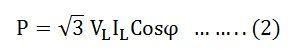
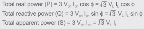
So, the total power in a three-phase balanced load system, regardless of the connection type—whether star-connected or delta-connected—is expressed by the relation:
√3 VLILCosϕ
Its units are kilowatts (kW) or watts (W).
Apparent power is expressed as: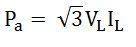
The unit of apparent power is kilovolt-ampere (kVA) or volt-ampere (VA).
Similarly, reactive power is defined by the equation: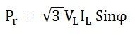
Its units are kilovolt-ampere reactive (kVAR) or volt-ampere reactive (VAR).
Generating Three-Phase Power
Three-phase power originates from a generator with three identical coils, spaced 120° apart electrically. As these coils rotate within a magnetic field (or the field rotates around stationary coils), three equal EMFs are induced, each offset by 120°. Represented mathematically:
- e_a = E_m × sin(ωt)
- e_b = E_m × sin(ωt - 120°)
- e_c = E_m × sin(ωt - 240°)
Here, E_m is the maximum EMF, and ω is the angular velocity.
Phase Sequence in Three-Phase Systems
The order in which the three phases reach their peak voltages is called the phase sequence (e.g., A-B-C or A-C-B). This sequence determines the direction of rotation in motors. A reversed sequence can reverse motor direction, making it critical to maintain consistency in power distribution and equipment operation.
Measuring Power in Three-Phase Circuits
Power measurement employs two techniques:
- Two-Wattmeter Method: Two wattmeters measure power across different lines, and their sum provides the total power in a three-phase system.
- One-Wattmeter Method: Used in four-wire systems with a neutral, a single wattmeter in a star configuration directly indicates total power.
Power Factor Correction in Three-Phase Circuits
The power factor (cos φ) reflects how efficiently power is utilized. A low power factor increases reactive power, reducing efficiency. In three-phase systems, capacitors or synchronous condensers are often added to correct the power factor, minimizing energy losses and improving system performance.
Benefits of Three-Phase Systems
Three-phase power offers distinct advantages:
- Higher Power Transmission: Delivers nearly double the power of single-phase systems with similar conductor sizes.
- Enhanced Motor Efficiency: Produces a rotating magnetic field for uniform torque in motors.
- Balanced Operation: Maintains consistent currents and voltages, reducing wear and losses.
- Flexibility: Easily converts to single-phase power or scales up with additional phases.
- Lower Losses: Reduced current lowers I²R losses during transmission.
Conclusion
Three-phase power is a game-changer for delivering electricity efficiently and reliably. It keeps power steady, handles big loads like those in factories and data centers, and saves money by using smaller wires. Whether it’s powering motors smoothly or cutting energy losses, three-phase systems outshine single-phase power for today’s high-tech world. Understanding how it works—from generation to measurement—helps make the most of this smart solution for modern energy needs.
|
76 videos|152 docs|62 tests
|
FAQs on Power In Three Phase Circuit - Network Theory (Electric Circuits) - Electrical Engineering (EE)
| 1. What are the main advantages of using three-phase power over single-phase power? |  |
| 2. How is power calculated in a three-phase circuit? | |
| 3. What is phase sequence, and why is it important in three-phase systems? | |
| 4. How can power factor correction be applied in three-phase circuits? | |
| 5. What are the common applications of three-phase power systems? | |


Sample Paper
,Free
,Objective type Questions
,Viva Questions
,shortcuts and tricks
,past year papers
,video lectures
,Important questions
,Semester Notes
,Exam
,MCQs
,Power In Three Phase Circuit | Network Theory (Electric Circuits) - Electrical Engineering (EE)
,practice quizzes
,study material
,Extra Questions
,Power In Three Phase Circuit | Network Theory (Electric Circuits) - Electrical Engineering (EE)
,ppt
,mock tests for examination
,Summary
,Previous Year Questions with Solutions
,Power In Three Phase Circuit | Network Theory (Electric Circuits) - Electrical Engineering (EE)
;


Power In Three Phase Circuit Free PDF Download
Importance of Power In Three Phase Circuit
Power In Three Phase Circuit Notes
Power In Three Phase Circuit Electrical Engineering (EE) Questions
Study Power In Three Phase Circuit on the App
|
© EduRev
|
Education Revolution
|


|


