How magnetically coupled circuits are used in transformers ? | Network Theory (Electric Circuits) - Electrical Engineering (EE) PDF Download
| Table of contents |
|
| Introduction |
|
| Mutual Inductance |
|
| Coupling Coefficient (k) |
|
| Dot Conversion |
|
| Equivalent Circuit Representation |
|
| Application of Voltage Transformation |
|
| Conclusion |
|

Introduction
Magnetically coupled circuits are integral to network theory, forming the basis of transformer operation. These circuits involve two or more coils linked by a magnetic field, where energy transfers via mutual inductance without direct electrical connection. Transformers, a primary application, use this principle to step up or step down voltages, relying on electromagnetic induction driven by alternating currents. Understanding how magnetically coupled circuits function in transformers is key to analyzing power systems and electrical networks, blending magnetic and electrical phenomena into practical engineering solutions.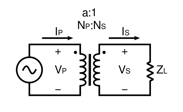
Mutual Inductance
Mutual inductance (M) is the cornerstone of magnetically coupled circuits, defining how a changing current in one coil induces voltage in another through a shared magnetic field. It’s expressed as the induced voltage in the secondary coil (V2) being equal to M times the rate of current change in the primary coil (di1/dt), based on Faraday’s Law. In transformers, this process is enhanced by a ferromagnetic core, such as iron, which concentrates the flux and increases M, ensuring efficient energy transfer. For instance, in a power transformer, a high mutual inductance means nearly all the magnetic energy from the primary winding reaches the secondary, directly influencing the output voltage. This mechanism is critical, as it allows transformers to function without physical connections, making mutual inductance the key to their operation and effectiveness in electrical networks.
Coupling Coefficient (k)
The coupling coefficient (k) measures how effectively magnetic flux links the coils in a coupled circuit, ranging from 0 (no coupling) to 1 (perfect coupling), and is calculated as M divided by the square root of the product of the self gave-inductances of the coils (L1 and L2). In transformers, k is designed to be close to 1, thanks to the iron core that minimizes flux leakage—uncoupled flux that doesn’t reach the secondary coil. A high k, such as 0.98 in well-designed transformers, ensures maximum energy transfer and efficiency, while a lower k, as seen in air-core coils, leads to losses like heat dissipation. For example, leakage flux in a poorly constructed transformer reduces performance, highlighting k’s role in optimization. This parameter is thus a critical design factor, balancing physical construction with energy transfer efficiency in transformer applications
Dot Conversion
The dot convention is a practical notation in magnetically coupled circuits, using dots on coil terminals to indicate the polarity of induced voltages relative to current direction. If current enters the dotted end of the primary coil, the induced voltage in the secondary is positive at its dotted end; if it enters the undotted end, the polarity reverses. In transformers, this ensures the secondary voltage aligns correctly with the primary—crucial for determining whether the output aids or opposes the input, as in step-up or step-down configurations. For instance, misinterpreting the dots in a circuit diagram could lead to phase errors, disrupting network analysis. By simplifying the writing of equations and ensuring accurate polarity, the dot convention is indispensable for modeling transformer behavior and maintaining consistency in multi-coil systems.
Equivalent Circuit Representation
The equivalent circuit representation transforms the complex interactions of magnetically coupled circuits into a solvable electrical model, critical for transformer analysis. It includes primary and secondary resistances (R1, R2) for winding losses, leakage inductances (L1 minus M, L2 minus M) for uncoupled flux, mutual inductance (M) for coupled flux, and an ideal transformer with a turns ratio (N1:N2). This model allows engineers to calculate currents, voltages, and losses under real-world conditions, such as when a transformer powers a load with copper and core losses. For example, in a 220V to 11V transformer, the equivalent circuit predicts secondary current and voltage drops, factoring in imperfections. By bridging magnetic phenomena to electrical terms, this representation enables systematic simulation and troubleshooting, making it a powerful tool in network theory and transformer design
Application of Voltage Transformation
oltage transformation is the practical outcome of magnetically coupled circuits in transformers, adjusting AC voltage levels based on the turns ratio, where the secondary voltage (V2) equals the primary voltage (V1) times the ratio of secondary turns (N2) to primary turns (N1), with current scaling inversely to conserve power. More turns on the secondary coil step up voltage, while fewer turns step it down, driven by the proportional linkage of magnetic flux. In power systems, this enables stepping up voltage (e.g., 11kV to 400kV) for efficient transmission with reduced resistive losses, then stepping it down (e.g., to 230V) for household use. Though losses like hysteresis and eddy currents slightly reduce efficiency, high coupling minimizes these effects. This adaptability makes transformers essential for scalable electricity distribution, meeting the diverse needs of generation, transmission, and consumption in modern power networks.
In transformers, magnetically coupled circuits operate through mutual inductance, where an AC-driven primary coil creates a dynamic magnetic field. This field, channeled by a core, induces voltage in the secondary coil proportional to the turns ratio and coupling efficiency (k). The dot convention ensures polarity alignment, critical for circuit consistency, while the equivalent circuit model translates magnetic effects into electrical terms for analysis. Voltage transformation, the end goal, leverages these principles to adjust AC levels efficiently—high voltage for transmission, low for usage—making transformers indispensable in power systems. Each element, from M to k, interlocks to optimize energy transfer, showcasing the elegance of coupled circuits in practical engineering.
Conclusion
Magnetically coupled circuits underpin transformer functionality in network theory, facilitating energy transfer through mutual inductance and precise magnetic linkage. Expanded insights into mutual inductance, coupling coefficient, dot convention, equivalent circuits, and voltage transformation reveal their depth and utility. These concepts enable transformers to efficiently manage voltage across electrical networks, from power plants to households. A thorough grasp of these topics empowers engineers to design and analyze transformers, ensuring reliable, adaptable power systems for modern society.|
76 videos|152 docs|62 tests
|
FAQs on How magnetically coupled circuits are used in transformers ? - Network Theory (Electric Circuits) - Electrical Engineering (EE)
| 1. What is mutual inductance and why is it important in transformers? |  |
| 2. How is the coupling coefficient (k) defined and what does it indicate in transformer design? | |
| 3. What does the L2 dot convention represent in transformers? | |
| 4. How can the equivalent circuit representation of transformers aid in understanding their function? | |
| 5. In what ways are transformers utilized in voltage transformation applications? | |


practice quizzes
,study material
,How magnetically coupled circuits are used in transformers ? | Network Theory (Electric Circuits) - Electrical Engineering (EE)
,Sample Paper
,past year papers
,Summary
,Semester Notes
,Previous Year Questions with Solutions
,ppt
,mock tests for examination
,How magnetically coupled circuits are used in transformers ? | Network Theory (Electric Circuits) - Electrical Engineering (EE)
,shortcuts and tricks
,Important questions
,Exam
,How magnetically coupled circuits are used in transformers ? | Network Theory (Electric Circuits) - Electrical Engineering (EE)
,MCQs
,Free
,Objective type Questions
,video lectures
,Viva Questions
,Extra Questions
;


How magnetically coupled circuits are used in transformers ? Free PDF Download
Importance of How magnetically coupled circuits are used in transformers ?
How magnetically coupled circuits are used in transformers ? Notes
How magnetically coupled circuits are used in transformers ? Electrical Engineering (EE) Questions
Study How magnetically coupled circuits are used in transformers ? on the App
|
© EduRev
|
Education Revolution
|


|


within 7 days!