Series RLC Circuit Resonance Frequency | Network Theory (Electric Circuits) - Electrical Engineering (EE) PDF Download

In a series RLC circuit, three components—a resistor (R), an inductor (L), and a capacitor (C)—are connected one after another. Resonance happens when the opposing reactive effects of the inductor and capacitor balance each other out, leaving the circuit purely resistive. At this point, the circuit displays unique characteristics, like reaching peak current and having the lowest impedance. Grasping the concept of resonance in a series RLC circuit is key to designing and evaluating a wide range of electronic systems and devices.
or
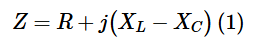
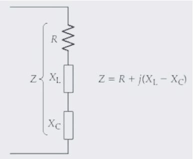
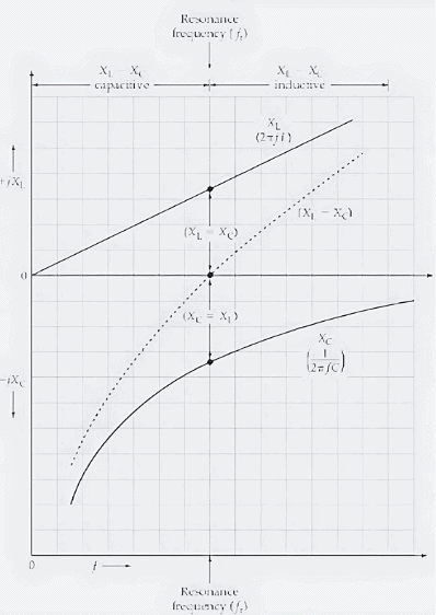
The impedance of the circuit hinges on the frequency of the alternating supply, thanks to the formulas XL = 2πfL for inductive reactance and XC = 1/(2πfC) for capacitive reactance, as shown in Figure 1(b). In Figure 2, you can see jXL and -jXC graphed against supply frequency. Since XL rises directly with frequency, the inductive reactance starts at zero and climbs steadily upward in a straight line as frequency increases. On the flip side, capacitive reactance XC, being inversely tied to frequency, behaves quite differently—it’s astronomically high at low frequencies and drops sharply as frequency rises, though it never quite hits zero. This gives the plot of (-jXC) versus frequency its distinctive curved shape, as depicted.
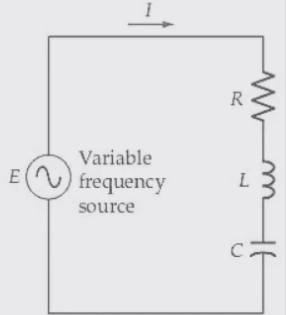 (a) Series RLC circuit with a variable frequency source.
 (b) XL and XC vary with the frequency of the voltage source.
So this,
In a series RLC circuit with a variable frequency source, XL becomes equal to XC at a particular frequency, known as the resonance frequency. The circuit impedance is then equal to R.
For this,
A plot of +jXL and -jXC versus frequency for a series RLC circuit shows that at a particular frequency (fr), XL = XC, and consequently (XL = XC) = 0. The frequency fr is known as the resonance frequency for the circuit.
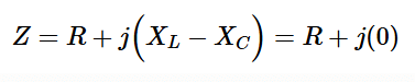
In a series RLC circuit, the total reactance is calculated as (XL - XC). At lower frequencies, XL is significantly smaller than XC, making the total reactance predominantly capacitive. At higher frequencies, where XL exceeds XC by a wide margin, the total reactance shifts to being mostly inductive. There’s a specific frequency, labeled fr, where XL and XC are exactly equal in value. At this point, the impedance of the series RLC circuit simplifies significantly.
or
When this happens, the circuit enters a state called electrical resonance, and the frequency where XL matches XC is termed the resonance frequency (fr).
In a series RLC circuit, the resonance frequency is the point where XL equals XC.
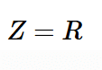
At frequencies below and above resonance, the reactance (X = XL - XC) takes on significant values, leaning either inductive or capacitive. As a result, when you plot the circuit’s impedance (from Equation 1) against frequency, you’ll notice it spikes to high levels on either side of the resonance frequency. Right at resonance, though, it drops to its lowest point, where Z simply equals R.
For a series RLC circuit, impedance hits its minimum at the resonance frequency.
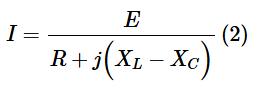
Current at ResonanceThe current in the series RLC circuit is determined from
or
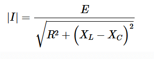
Where I is the numerical value of the current without reference to its phase angle. Thus, at resonance, when XL=XC, the current equation becomes

A typical graph of current versus frequency for the series RLC circuit is shown in the figure. The current drops to a minimum at frequencies above and below resonance but spikes sharply at resonance as the impedance reaches its lowest point. This current-versus-frequency graph is often called the circuit’s frequency response curve.
Phase Angle
As observed, the impedance of the series RLC circuit is predominantly capacitive at frequencies well below resonance. This causes the circuit current to lead the applied voltage by a phase angle of roughly 90°. On the other hand, at frequencies far above resonance, the impedance becomes mostly inductive, shifting the current’s phase angle to about -90°. The graph of phase angle versus frequency for the series RLC circuit illustrates this shift: starting with a 90° leading phase angle at low frequencies, dropping to 0° at the resonance frequency, and transitioning to a 90° lagging phase angle beyond fr.
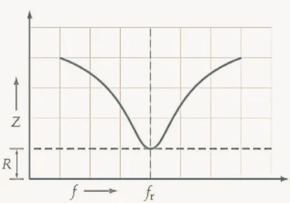 (a) Graph of impedance versus frequency
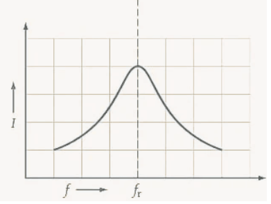
(b) Graph of current versus frequency
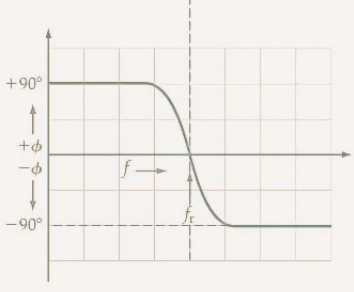 (c) Graph of current phase angle versus frequencySo this ,
Graphs of impedance, current, and phase angle versus frequency for a series RLC circuit. Because Z=R+j(XL-XC), the impedance dips to R at fr, and the current peaks. The current phase angle is zero at fr, becomes leading below fr and is lagging above fr.
Resonance Frequency
The frequency at which resonance occurs is easily calculated by equating XL and XC:
Or
So
Giving
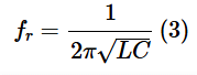
When L and C are in henrys and farads, respectively, Equation 2 gives fr in hertz.
|
76 videos|152 docs|62 tests
|
FAQs on Series RLC Circuit Resonance Frequency - Network Theory (Electric Circuits) - Electrical Engineering (EE)
| 1. What is the resonance frequency in a series RLC circuit? |  |
| 2. How does frequency affect the impedance of a series RLC circuit? | |
| 3. What happens to the circuit at frequencies below and above the resonance frequency? | |
| 4. How can you determine the quality factor (Q) of a series RLC circuit? | |
| 5. Why is it important to understand the frequency effect on circuit impedance in practical applications? | |


shortcuts and tricks
,Series RLC Circuit Resonance Frequency | Network Theory (Electric Circuits) - Electrical Engineering (EE)
,Important questions
,Sample Paper
,Free
,mock tests for examination
,Extra Questions
,study material
,Series RLC Circuit Resonance Frequency | Network Theory (Electric Circuits) - Electrical Engineering (EE)
,practice quizzes
,past year papers
,Viva Questions
,Previous Year Questions with Solutions
,Exam
,MCQs
,Objective type Questions
,video lectures
,Semester Notes
,ppt
,Summary
,Series RLC Circuit Resonance Frequency | Network Theory (Electric Circuits) - Electrical Engineering (EE)
;


Series RLC Circuit Resonance Frequency Free PDF Download
Importance of Series RLC Circuit Resonance Frequency
Series RLC Circuit Resonance Frequency Notes
Series RLC Circuit Resonance Frequency Electrical Engineering (EE) Questions
Study Series RLC Circuit Resonance Frequency on the App
|
© EduRev
|
Education Revolution
|


|


