Electrical Engineering (EE) Exam  >  Electrical Engineering (EE) Tests  >  GATE Electrical Engineering (EE) Mock Test Series 2026  >  Test: Measurement of Power & Energy- 2 - Electrical Engineering (EE) MCQ

Test: Measurement of Power & Energy- 2 - Electrical Engineering (EE) MCQ


Test Description

15 Questions MCQ Test GATE Electrical Engineering (EE) Mock Test Series 2026 - Test: Measurement of Power & Energy- 2

Test: Measurement of Power & Energy- 2 for Electrical Engineering (EE) 2025 is part of GATE Electrical Engineering (EE) Mock Test Series 2026 preparation. The Test: Measurement of Power & Energy- 2 questions and answers have been prepared according to the Electrical Engineering (EE) exam syllabus.The Test: Measurement of Power & Energy- 2 MCQs are made for Electrical Engineering (EE) 2025 Exam. Find important definitions, questions, notes, meanings, examples, exercises, MCQs and online tests for Test: Measurement of Power & Energy- 2 below.
Solutions of Test: Measurement of Power & Energy- 2 questions in English are available as part of our GATE Electrical Engineering (EE) Mock Test Series 2026 for Electrical Engineering (EE) & Test: Measurement of Power & Energy- 2 solutions in Hindi for GATE Electrical Engineering (EE) Mock Test Series 2026 course. Download more important topics, notes, lectures and mock test series for Electrical Engineering (EE) Exam by signing up for free. Attempt Test: Measurement of Power & Energy- 2 | 15 questions in 45 minutes | Mock test for Electrical Engineering (EE) preparation | Free important questions MCQ to study GATE Electrical Engineering (EE) Mock Test Series 2026 for Electrical Engineering (EE) Exam | Download free PDF with solutions
Test: Measurement of Power & Energy- 2 - Question 1

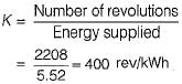
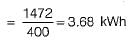
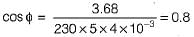
A 230 V, single phase, watt hour meter has a constant load of 4 A passing through it for 6 hours at unity at unity power factor. The meter disc makes 2208 revolutions during this period. If the number of revolutions made by the meter are 1472 when operating at 230 V and 5 A for 4 hours, then power factor of the load would be

Detailed Solution for Test: Measurement of Power & Energy- 2 - Question 1

Energy supplied = VI cosφ) x t x 10-3 kWh
= 230 x 4 x 1 x 6 x 10-3
= 5.52 kWh
Energy meter constant,

Energy consumed when the meter makes 1472 revolutions

Now, energy consumed
 VI cos φ x f x 10-3 kWh = 230 x 5 x cost}) x 4 x 10⁻³ kWh
= 3.68 kWh (As obtained above)
or, 
Hence, power factor of the load = 0.8

Test: Measurement of Power & Energy- 2 - Question 2

The declared constant of a 5 A, 220 V d.c. watthour meter is 3275 revolutions per kWh. The speed of the disc at full load is

Detailed Solution for Test: Measurement of Power & Energy- 2 - Question 2

Here, cos φ = 1 (for d.c. watthour meter) Energy supplied to the energy meter in kWh

∴ Energy supplied to the energy meter per minute = 
Given, energy meter constant, K = 3275 revolutions/kWh
∴ Disc speed in rpm = Energy supplied per minute x Energy meter constant

Test: Measurement of Power & Energy- 2 - Question 3

In an induction type energy meter, an increase in temperature results in

Detailed Solution for Test: Measurement of Power & Energy- 2 - Question 3

An increase in temperature is accompanied by a rise in resistance of ail copper and aluminium parts.

Test: Measurement of Power & Energy- 2 - Question 4

A dynamometer wattmeter measures power in a 50 Hz, single phase circuit without error, at all power factors. The resistance of the voltage coil and its series resistance are 400 Ω and 10,000 Ω, respectively. The series resistance has a distributed self-capacitance equivalent to a shunt capacity of 20 pF.What is the self inductance of the pressure coil?

Detailed Solution for Test: Measurement of Power & Energy- 2 - Question 4

Given, Rp = 400Ω,
RS = 10,000 Ω
CC = 20 pF
Self inductance of the pressure coil is given by
Lp = CC x RS2
= 20 x 10-12 x (104)2
= 20 x 10-4 = 2 mH

Test: Measurement of Power & Energy- 2 - Question 5

Assertion (A): For measuring the power factor of the load in case of a two-wattmeter method, load may be balanced or unbalanced.
Reason (R): For measuring the power in a three- phase circuit, load may be balanced or unbalanced, source may be balanced or unbalanced but there must be three-phase load connected to three-phase source via three- phase wires.​

Detailed Solution for Test: Measurement of Power & Energy- 2 - Question 5

Measurement of power factor with the help of two-wattmeter method can be done only if load is balanced. Hence, assertion is not true. Reason is a correct statement.

Test: Measurement of Power & Energy- 2 - Question 6

The voltage and current in a circuit are given by, v(t) = 5 + 2 sin(ωt + 30°) + 10 sin(3ωt - 60°) and i(t) = 10 + 5 sinωt + 8 sin(2ωt-30°)
The total power consumed in the circuit is

Detailed Solution for Test: Measurement of Power & Energy- 2 - Question 6
  • Voltage: v(t) = 5 + 2 sin(ωt + 30°) + 10 sin(3ωt - 60°)

  • Current: i(t) = 10 + 5 sin(ωt) + 8 sin(2ωt - 30°)

  • Step 1: Calculate the instantaneous power, p(t)

    Instantaneous power is given by:

    p(t) = v(t) × i(t)

    Substitute the given expressions for v(t) and i(t):

    p(t) = (5 + 2 sin(ωt + 30°) + 10 sin(3ωt - 60°)) × (10 + 5 sin(ωt) + 8 sin(2ωt - 30°))

    Step 2: Find the average power

    The average power is the mean of the instantaneous power over a period T. For sinusoidal functions, the average power is calculated by considering only the constant terms (the DC components) and the terms with the same frequency (as the cross terms average to zero over a period).

  • The DC components of voltage and current are:

    • Voltage DC component: 5

    • Current DC component: 10

  • The power from these DC components is:

    P_DC = 5 × 10 = 50 watt

    For the sinusoidal terms, we consider the RMS (root mean square) values:

  • For 2 sin(ωt + 30°) and 5 sin(ωt), the RMS values are:

    • Voltage RMS: 2

    • Current RMS: 5

  • The power from the first sinusoidal component is:

    P_1 = 2 × 5 × cos(30°) = 5√3 ≈ 8.660 watt

  • For 10 sin(3ωt - 60°) and 8 sin(2ωt - 30°), these have different frequencies, so they don’t contribute to the power directly.

  • Thus, the total power consumed in the circuit is the sum of the DC power and the power from the first sinusoidal component:

    P_total = 50 + 8.660 ≈ 58.66 watt

    However, this value doesn't match the options provided, so the correct answer is:

    d) none of these

Test: Measurement of Power & Energy- 2 - Question 7

In an electrodynamometer type wattmeter
1. moving coil is iron cored.
2. fixed coil is air cored.
3. air friction damping is used.
4. the fixed coil is connected across the load.
5. the moving coil is connected in series with the load.

Q. Which of the above statements is/are true?

Detailed Solution for Test: Measurement of Power & Energy- 2 - Question 7

In an electrodynamometer type wattmeter:
• Both fixed and moving coils are air cored.
• Air friction damping is used due to low value of operating magnetic field.
• The moving coil is connected across the load.
• The fixed coil is connected is series with the load.

Test: Measurement of Power & Energy- 2 - Question 8

Assertion (A): A wattmeter must be used for the measurement of power in a.c. circuit instead of merely an ammeter and a voltmeter.
Reason (R): Wattmeter measures average active and reactive powers.

Detailed Solution for Test: Measurement of Power & Energy- 2 - Question 8

A wattmeter must be used for the measurement of power in a.c. circuit instead of merely an ammeter and a voltmeter because the power factor can’t be measured with the help of voltmeter and ammeter.
Wattmeter measures average active power not average reactive power. Hence, reason is not a correct statement.

Test: Measurement of Power & Energy- 2 - Question 9

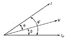
Assertion (A): An electrodynamometer type wattmeter reads low when the load power factor is leading.
Reason (R): The effect of pressure coil inductance is to increase the phase angle between load current and pressure coil current when the load power factor is leading.

Detailed Solution for Test: Measurement of Power & Energy- 2 - Question 9

In
In the above phasor diagram
I = load current and
IP = Pressure coil current

We know that, measured power is

At leading power factor of load, angle (φ + β) is increased, therefore cos(φ + β) is reduced. Hence, wattmeter reads low at leading p.f, load.

Test: Measurement of Power & Energy- 2 - Question 10

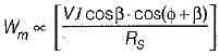
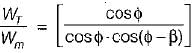
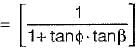
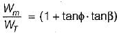
 The ratio of measured power to true power in case of an electrodynamometer type wattmeter is given by (β = internal angle of pressure coil circuit)

Detailed Solution for Test: Measurement of Power & Energy- 2 - Question 10

We have:


or,

Test: Measurement of Power & Energy- 2 - Question 11

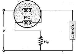
Assertion (A): Phantom loading of energy meter consists of supplying the fixed coil circuit from a circuit of required normal voltage, and the moving coil circuit from a separate low voltage supply.
Reason (R): When the current rating of a meter under test is high, a test with actual loading arrangement would involve a considerable waste of power due to which phantom or fictious loading is done.

Detailed Solution for Test: Measurement of Power & Energy- 2 - Question 11

Phantom loading consists of supplying the pressure coil circuit (or moving coil circuit) from a circuit of required normal voltage, and the current circuit (or fixed coil circuit) from a separate low voltage supply. Hence, assertion is not true.
Reason is a correct statement.

Test: Measurement of Power & Energy- 2 - Question 12

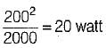
A dynamometer wattmeter with its voltage coil connected across the load side of the instrument reads 250 W, If the load voltage be 200 V, what power is being taken by the load?​
(The voltage coil has a resistance of 2000 Ω)

Detailed Solution for Test: Measurement of Power & Energy- 2 - Question 12


Power loss in the voltage coil = 
instrument reading = 250 watt
∴ Actual load = 250 - 20
= 230 watt

Test: Measurement of Power & Energy- 2 - Question 13

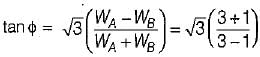
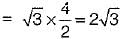
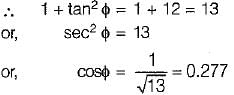
The power flowing in a 3- φ, 3-wire, balanced load system is measured by the two-wattmeter method. The reading on wattmeter -A is 3 kW and on wattmeter -B is-1 kW. The factor of the load is

Detailed Solution for Test: Measurement of Power & Energy- 2 - Question 13


Test: Measurement of Power & Energy- 2 - Question 14

Holes are filled on the opposite side of the disc of an induction type energy meter to

Detailed Solution for Test: Measurement of Power & Energy- 2 - Question 14

Cripping is due to over compensation provided to the running friction. To avoid it holes are made on opposite side of the disc of the energy meter.

Test: Measurement of Power & Energy- 2 - Question 15

Two-wattmeter method is employed to measure power in a 3-phase balanced system with the current coils connected in the A and C lines. The phase sequence is ABC. If the wattmeter with its current coil in A-phase line reads zero, then the power factor of the 3-phase load will be

Detailed Solution for Test: Measurement of Power & Energy- 2 - Question 15

When power factor = 0.5 (φ = 60°), then one wattmeter will read zero. The load will be lagging in nature.
W1 = VLIL cos (30 + φ) 
and W2 = VLIL cos (30 - φ)
For φ = 60°, W1 = 0 watt

26 docs|257 tests
Information about Test: Measurement of Power & Energy- 2 Page
In this test you can find the Exam questions for Test: Measurement of Power & Energy- 2 solved & explained in the simplest way possible. Besides giving Questions and answers for Test: Measurement of Power & Energy- 2, EduRev gives you an ample number of Online tests for practice
Download as PDF