


All Exams >
Mechanical Engineering >
Fluid Mechanics for Mechanical Engineering >
All Questions
All questions of Flow Through Pipes for Mechanical Engineering Exam
Maximum efficiency of transmission of power through a pipe is- a)25%
- b)66.66%
- c)33.3%
- d)50%
Correct answer is option 'B'. Can you explain this answer?
Maximum efficiency of transmission of power through a pipe is
a)
25%
b)
66.66%
c)
33.3%
d)
50%
|
|
Nayanika Yadav answered |
Efficiency of power transmission is given by
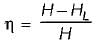
For maximum efficiency

We get
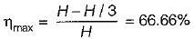
For maximum efficiency
We get

Power transmitted through a pipe is given by
where
w = specific weight of the fluid flowing through pipe
Q = discharge, m3/s- a)wQH
- b)wQHL
- c)wQ(H - HL)
- d)wQ(H + HL)
Correct answer is option 'C'. Can you explain this answer?
Power transmitted through a pipe is given by
where
w = specific weight of the fluid flowing through pipe
Q = discharge, m3/s
where
w = specific weight of the fluid flowing through pipe
Q = discharge, m3/s
a)
wQH
b)
wQHL
c)
wQ(H - HL)
d)
wQ(H + HL)
|
|
Anmol Saini answered |
Power transmitted through a pipe (When HL is frictional head)
P = wQ(H - HL)
P = wQ(H - HL)
Consider the following statements:
1. Pipe network analysis is normally necessary in analyzing flow in pipes at city water systems,
2. Hardy-cross method of solving pipe network is a method of successive approximations and is not a direct method.
3. The network must satisfy the momentum equation because the flow in each pipe satisfies the head loss equation.
4. Principle of continuity is satisfied in a pipe network..Select the correct statments:- a)1, 2 and 3
- b)2, 3 and 4
- c)1, 3 and 4
- d)1, 2 and 4
Correct answer is option 'B'. Can you explain this answer?
Consider the following statements:
1. Pipe network analysis is normally necessary in analyzing flow in pipes at city water systems,
2. Hardy-cross method of solving pipe network is a method of successive approximations and is not a direct method.
3. The network must satisfy the momentum equation because the flow in each pipe satisfies the head loss equation.
4. Principle of continuity is satisfied in a pipe network..
Select the correct statments:
a)
1, 2 and 3
b)
2, 3 and 4
c)
1, 3 and 4
d)
1, 2 and 4

|
Gitanjali Menon answered |
Pipe Network Analysis
Statement 1: Pipe network analysis is normally necessary in analyzing flow in pipes at city water systems.
- Pipe network analysis is an important tool used in hydraulic engineering to determine the flow rates, pressure losses, and head losses in a network of pipes.
- It is particularly important in city water systems where the network can be complex, and the demand for water can be high.
- By analyzing the network, engineers can optimize the design to minimize energy consumption, reduce pipe sizes, and ensure that the pressure and flow requirements are met.
Hardy-Cross Method
Statement 2: Hardy-cross method of solving pipe network is a method of successive approximations and is not a direct method.
- The Hardy-Cross method is a widely used method for solving pipe networks.
- It is an iterative method, which means that the solution is obtained by successive approximations.
- The method involves balancing the head losses around each loop in the network and adjusting the flow rates in each pipe until a solution is reached.
- While the method is not a direct method, it is relatively simple to use, and it can be applied to networks of any size and complexity.
Momentum Equation and Principle of Continuity
Statement 3: The network must satisfy the momentum equation because the flow in each pipe satisfies the head loss equation.
- The momentum equation is a fundamental principle in fluid mechanics that relates the forces acting on a fluid to its mass, velocity, and acceleration.
- In a pipe network, the momentum equation must be satisfied because the flow in each pipe is subject to frictional losses, which cause a loss of momentum.
- The head loss equation, which is used in pipe network analysis, is derived from the momentum equation and is based on the assumption that the flow is steady and incompressible.
- By satisfying the momentum equation, engineers can ensure that the flow rates and pressures in the network are consistent with the physical laws of fluid mechanics.
Statement 4: Principle of continuity is satisfied in a pipe network.
- The principle of continuity is another fundamental principle in fluid mechanics that states that the mass flow rate of a fluid is constant at any given point in a pipe or duct.
- In a pipe network, the principle of continuity must be satisfied because the flow rates at each junction in the network must be balanced.
- The continuity equation, which is used in pipe network analysis, is based on the principle of continuity and is used to calculate the flow rates in each pipe.
- By satisfying the principle of continuity, engineers can ensure that the flow rates in the network are consistent with the physical laws of fluid mechanics.
Conclusion
- In summary, pipe network analysis is an important tool in hydraulic engineering, and the Hardy-Cross method is a widely used method for solving pipe networks.
- The momentum equation and principle of continuity are fundamental principles in fluid mechanics that must be satisfied in a pipe network to ensure that the flow rates and pressures are consistent with the physical laws of fluid mechanics.
The minor loss due to sudden contraction is due to- a)flow contraction
- b)expansion of flow after sudden contraction
- c)boundary friction
- d)cavitation
Correct answer is option 'B'. Can you explain this answer?
The minor loss due to sudden contraction is due to
a)
flow contraction
b)
expansion of flow after sudden contraction
c)
boundary friction
d)
cavitation
|
|
Akash Kapoor answered |
In sudden contraction, right after the sudden contraction Ac , a vena contracta is formed; and then, right after, the flow widens again to fill the entire pipe. The region between the wall interior pipe and the vena contracta will be a region of separated flow. The flow pattern after the vena contracta is similar to that after an abrupt enlargement and the loss is caused due to expansion of flow after sudden contraction.
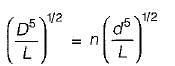
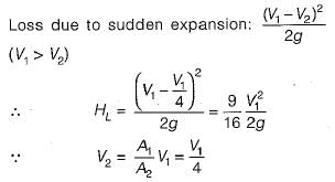
Three identical pipes of length L, diameter D and friction factor f, are connected in parallel between two reservoirs. The size of a pipe of length L and of same friction factor f, equivalent to the above pipes, is- a)D
- b)1.22 D
- c)1.55 D
- d)1.86 D
Correct answer is option 'C'. Can you explain this answer?
Three identical pipes of length L, diameter D and friction factor f, are connected in parallel between two reservoirs. The size of a pipe of length L and of same friction factor f, equivalent to the above pipes, is
a)
D
b)
1.22 D
c)
1.55 D
d)
1.86 D
|
|
Avinash Sharma answered |
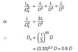
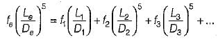
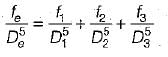
Equivalent pipe for the pipes in parallel:
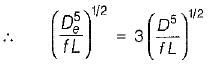
or
or De = 1.5518 D
or
or De = 1.5518 D
The diameter of the nozzle (d) for maximum transmission of power is given by
Where
D = Diameter of pipe
f = Darcy’s friction factor
l = Length of pipe
- a) d = (D5/8fl)1/2
- b)d = (D5/8fl)1/3
- c)d = (D5/8fl)1/5
- d)d = (D5/8fl)1/4
Correct answer is option 'D'. Can you explain this answer?
The diameter of the nozzle (d) for maximum transmission of power is given by
Where
D = Diameter of pipe
f = Darcy’s friction factor
l = Length of pipe
Where
D = Diameter of pipe
f = Darcy’s friction factor
l = Length of pipe
a)
d = (D5/8fl)1/2
b)
d = (D5/8fl)1/3
c)
d = (D5/8fl)1/5
d)
d = (D5/8fl)1/4

|
Nishanth Banerjee answered |
For maximum power transmission through nozzle:
Nozzle diameter
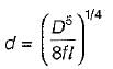
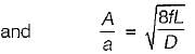
A = area of supply pipe
a = area of Nozzle
Nozzle diameter
A = area of supply pipe
a = area of Nozzle
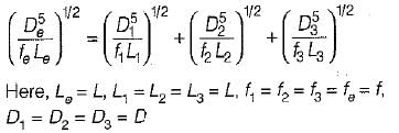
Three identical pipes of lenght L, diameter D and friction factor f, are connected in series between two reservoirs. The size of a pipe of length L and of the same friction factor f, equivalent to above pipeline, is- a)0.5 D
- b)0.8 D
- c)0.9 D
- d)D
Correct answer is option 'B'. Can you explain this answer?
Three identical pipes of lenght L, diameter D and friction factor f, are connected in series between two reservoirs. The size of a pipe of length L and of the same friction factor f, equivalent to above pipeline, is
a)
0.5 D
b)
0.8 D
c)
0.9 D
d)
D
|
|
Rajdeep Nambiar answered |

In network of pipes- a)the head loss around each elementary circuit must be zero
- b)the head loss in all circuits in the same
- c)the elevation of H.G.L is assumed for each junction
- d)elementary circuits are replaced by equivalent pipes
Correct answer is option 'A'. Can you explain this answer?
In network of pipes
a)
the head loss around each elementary circuit must be zero
b)
the head loss in all circuits in the same
c)
the elevation of H.G.L is assumed for each junction
d)
elementary circuits are replaced by equivalent pipes
|
|
Rounak Saini answered |
Head Loss in Network of Pipes
Head loss is a reduction in the total head (pressure) of a fluid as it flows through a network of pipes. To ensure efficient flow and pressure distribution in a network of pipes, certain considerations must be taken into account. These considerations include:
Elementary Circuits
An elementary circuit is a closed loop of pipes that starts and ends at the same point. In a network of pipes, the head loss around each elementary circuit must be zero. This means that the head loss in the circuit is the same as the head gain, resulting in no net loss of head. If the head loss around an elementary circuit is not zero, it can lead to an imbalance in the network, causing flow problems.
Equivalent Pipes
Elementary circuits can be replaced by equivalent pipes to simplify calculations. An equivalent pipe is a single pipe that has the same head loss as the elementary circuit it replaces. By replacing all the elementary circuits with equivalent pipes, the network can be reduced to a single pipe system, making it easier to calculate the head loss and flow rate.
Elevation of H.G.L
The H.G.L (hydraulic grade line) is an imaginary line that represents the pressure of the fluid in the network of pipes. The elevation of the H.G.L is assumed for each junction in the network to ensure that the flow is consistent throughout the system. This assumption helps to avoid problems with pressure imbalances and flow disruptions.
Head Loss in All Circuits
While the head loss around each elementary circuit must be zero, the head loss in all circuits in the network may not be the same. This is because different circuits may have different lengths, diameters, and fittings, resulting in varying head losses. However, the overall head loss in the network must be within an acceptable range to ensure efficient flow and pressure distribution.


A pipe has a welt rounded entrance from a reservoir. If the head loss at the entrance is expressed a the value of K would be about
- a)0.02
- b)0.2
- c)0.5
- d)1.0
Correct answer is option 'A'. Can you explain this answer?
A pipe has a welt rounded entrance from a reservoir. If the head loss at the entrance is expressed a the value of K would be about
the value of K would be abouta)
0.02
b)
0.2
c)
0.5
d)
1.0
|
|
Anjali Datta answered |
Head loss for well rounded entrance as compared to sharp cornered entrance is very small.
 The length of a pipe of 15 cm diameter 2fif {f = 0.03) equivalent to this loss is
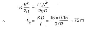
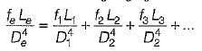
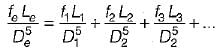
Two pipe systems in series are said to be equivalent when- a)the average diameter in both systems is the same. .
- b)the discharge under the same heacj is same in both systems,
- c)the average friction factor in both systems is the same.
- d)total length of the pipe is the same in both the systems.
Correct answer is option 'B'. Can you explain this answer?
Two pipe systems in series are said to be equivalent when
a)
the average diameter in both systems is the same. .
b)
the discharge under the same heacj is same in both systems,
c)
the average friction factor in both systems is the same.
d)
total length of the pipe is the same in both the systems.
|
|
Sahana Choudhary answered |
Equivalent Two Pipe Systems in Series
The question is related to the concept of equivalent two pipe systems in series. Let's discuss the correct answer, which is option 'B.'
Discharge under the Same Head in Both Systems
When two pipe systems are in series, they are said to be equivalent when the discharge under the same head is the same in both systems. This means that the flow rate of the fluid in both systems is the same when the pressure head is the same.
Reasoning
The reason behind this is that when two pipe systems are in series, the flow rate of the fluid remains constant, and the head loss is distributed between the two systems. Therefore, the discharge under the same head should be the same in both systems.
Other Options
The other options mentioned in the question are not correct because:
- Option 'A' - The average diameter of the pipe does not determine the equivalence of the two pipe systems in series because the diameter of the pipe affects the flow rate and head loss, which can be different in both systems.
- Option 'C' - The average friction factor of the pipe also affects the head loss, which can be different in both systems.
- Option 'D' - The total length of the pipe also affects the head loss, which can be different in both systems.
Conclusion
In conclusion, when two pipe systems are in series, they are said to be equivalent when the discharge under the same head is the same in both systems. This indicates that the flow rate of the fluid is the same in both systems when the pressure head is the same.
At a sudden expansion in a horizontal pipe- a)total energy line rises in the direction of flow
- b)velocity head increasing in the direction of flow
- c)H.G.L rises in the direction of flow
- d)T.E.L is below H.G.L
Correct answer is option 'C'. Can you explain this answer?
At a sudden expansion in a horizontal pipe
a)
total energy line rises in the direction of flow
b)
velocity head increasing in the direction of flow
c)
H.G.L rises in the direction of flow
d)
T.E.L is below H.G.L
|
|
Amar Desai answered |
Expansion in a Horizontal Pipe and the Effect on Energy Lines
When fluid flows through a pipe, it possesses different forms of energy, including pressure energy, kinetic energy, and potential energy. The fluid's total energy can be defined as the sum of these three energies. The energy lines illustrate the distribution of total energy along the pipe's length, while the hydraulic grade line (H.G.L) represents the pressure energy distribution.
At a sudden expansion in a horizontal pipe, the flow area increases, causing a change in the fluid's velocity and pressure distribution, resulting in the following effects:
H.G.L rises in the direction of flow
The hydraulic grade line (H.G.L) represents the pressure energy distribution, and it is a measure of the pressure head of the fluid. At a sudden expansion, the flow area increases, causing a decrease in the fluid's velocity and an increase in its pressure. This increase in pressure causes the H.G.L to rise in the direction of flow.
Total energy line rises in the direction of flow
The total energy line (T.E.L) represents the sum of all three forms of energy, including pressure, kinetic, and potential energies. At a sudden expansion, the flow area increases, causing a decrease in the fluid's velocity and an increase in pressure. This increase in pressure causes the T.E.L to rise in the direction of flow.
Velocity head decreasing in the direction of flow
The velocity head is the kinetic energy of the fluid per unit weight. At a sudden expansion, the flow area increases, causing a decrease in the fluid's velocity. This decrease in velocity causes the velocity head to decrease in the direction of flow.
Conclusion
In conclusion, at a sudden expansion in a horizontal pipe, the flow area increases, causing a decrease in the fluid's velocity and an increase in its pressure. This increase in pressure causes the H.G.L and T.E.L to rise in the direction of flow, while the velocity head decreases in the direction of flow.
In a pipeline, the H.G.L is above the pipe center line in the longitudinal section at point A and below the pipe center line at another point B.
From this it can be inferred that- a)negative pressure prevails at A and positive pressure prevails at B.
- b)positive pressure prevails at A and negative pressure prevails at B.
- c)positive pressure prevails at both A and B.
- d)negative pressure,prevails at both A and B
Correct answer is option 'B'. Can you explain this answer?
In a pipeline, the H.G.L is above the pipe center line in the longitudinal section at point A and below the pipe center line at another point B.
From this it can be inferred that
From this it can be inferred that
a)
negative pressure prevails at A and positive pressure prevails at B.
b)
positive pressure prevails at A and negative pressure prevails at B.
c)
positive pressure prevails at both A and B.
d)
negative pressure,prevails at both A and B

|
Bibek Mukherjee answered |
Explanation:
The given statement indicates that the hydraulic gradient line (H.G.L) is above the pipe center line at point A and below the pipe center line at point B. From this information, we can infer that:
1. Definition of H.G.L
The hydraulic gradient line (H.G.L) represents the total energy line in a pipeline. It is the line connecting the static head and the velocity head of the fluid in the pipeline.
2. Pressure Variation
When the H.G.L is above the pipe center line, it indicates that the pressure is negative or less than atmospheric pressure. Similarly, when the H.G.L is below the pipe center line, it indicates that the pressure is positive or greater than atmospheric pressure.
3. Point A
As per the given statement, the H.G.L is above the pipe center line at point A. Therefore, the pressure at point A is negative or less than atmospheric pressure.
4. Point B
On the other hand, the H.G.L is below the pipe center line at point B. Therefore, the pressure at point B is positive or greater than atmospheric pressure.
5. Conclusion
Hence, from the above observations, we can conclude that positive pressure prevails at point A and negative pressure prevails at point B. Therefore, the correct answer is option 'B'.
In summary, the given statement indicates the variation in pressure along a pipeline, based on the position of the hydraulic gradient line (H.G.L) relative to the pipe center line. It highlights the importance of the H.G.L in determining the pressure distribution in a pipeline.


Chapter doubts & questions for Flow Through Pipes - Fluid Mechanics for Mechanical Engineering 2025 is part of Mechanical Engineering exam preparation. The chapters have been prepared according to the Mechanical Engineering exam syllabus. The Chapter doubts & questions, notes, tests & MCQs are made for Mechanical Engineering 2025 Exam. Find important definitions, questions, notes, meanings, examples, exercises, MCQs and online tests here.
Chapter doubts & questions of Flow Through Pipes - Fluid Mechanics for Mechanical Engineering in English & Hindi are available as part of Mechanical Engineering exam.
Download more important topics, notes, lectures and mock test series for Mechanical Engineering Exam by signing up for free.
Fluid Mechanics for Mechanical Engineering
56 videos|154 docs|75 tests
|
|
© EduRev
|
Education Revolution
|


|


Signup on EduRev and stay on top of your study goals
10M+ students crushing their study goals daily