


All Exams >
Mechanical Engineering >
Fluid Mechanics for Mechanical Engineering >
All Questions
All questions of Hydraulic Machines: Turbines & Pumps for Mechanical Engineering Exam

In the selection of turbine by specific speed or head, which one of the following statements is not correct?
- a)For specific speed 10-35, Kaplan turbines
- b)For specific speed 60-300, Francis turbines
- c)For head 50-150 m, Francis turbines
- d)For head above 300 m, Pelton wheel
Correct answer is option 'A'. Can you explain this answer?
In the selection of turbine by specific speed or head, which one of the following statements is not correct?
a)
For specific speed 10-35, Kaplan turbines
b)
For specific speed 60-300, Francis turbines
c)
For head 50-150 m, Francis turbines
d)
For head above 300 m, Pelton wheel

|
Abhay Kapoor answered |
- For specific speed 10-35, Kaplan turbines
This statement is incorrect because Kaplan turbines are designed for much higher specific speeds. The correct range for Kaplan turbines is generally from 300 to 1000 (in metric units), making this option inaccurate.
The speed factor of a Peiton turbine for maximum efficiency condition is about- a)0.46
- b)0.50
- c)0.86
- d)0.95
Correct answer is option 'A'. Can you explain this answer?
The speed factor of a Peiton turbine for maximum efficiency condition is about
a)
0.46
b)
0.50
c)
0.86
d)
0.95

|
Diya Ahuja answered |
**Explanation:**
The Peiton turbine is a type of hydraulic turbine that operates based on the principle of impulse. Its efficiency depends on various factors, including the speed factor.
The speed factor, denoted by λ (lambda), is a dimensionless parameter that represents the ratio of the actual speed of the turbine runner to the ideal speed at which it should operate for maximum efficiency. It is defined as:
λ = (n * D) / (g * H)^0.5
Where:
- λ = Speed factor
- n = Runner speed in rpm
- D = Runner diameter in meters
- g = Acceleration due to gravity (9.81 m/s^2)
- H = Water head (the difference in water level between the inlet and outlet of the turbine) in meters
For maximum efficiency, the speed factor should be around 0.46.
**Reasoning:**
The speed factor determines the relative velocity of the water at the inlet of the turbine runner. At maximum efficiency, the water should strike the runner blades at an angle of 165 degrees.
If the speed factor is too low (below 0.46), the water strikes the runner blades at a wider angle, resulting in inefficient use of the water's kinetic energy.
If the speed factor is too high (above 0.46), the water strikes the runner blades at a narrower angle, leading to excessive turbulence and energy losses.
Therefore, the speed factor of a Peiton turbine for maximum efficiency condition is approximately 0.46.
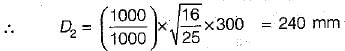
Two geometrically similar pumps £re running at the same speed of 100 rpm'arid lifting water against the heads of 25 m and 16 m respectively. First pump is having an impeller diameter of 300 mm. The impeller diameter of second pump shall be- a)192 mm
- b)240 mm
- c)300 mm
- d)469 mm
Correct answer is option 'B'. Can you explain this answer?
Two geometrically similar pumps £re running at the same speed of 100 rpm'arid lifting water against the heads of 25 m and 16 m respectively. First pump is having an impeller diameter of 300 mm. The impeller diameter of second pump shall be
a)
192 mm
b)
240 mm
c)
300 mm
d)
469 mm
|
|
Arjun Menon answered |
Equating head coefficients, we get,

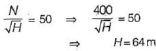
A Francis turbine working at 400 rpm has a unit speed of 50 rpm and develops 500 kW of power. What is the effective head under which this turbine operates?- a)62.5 m
- b)64.0 m
- c)40.0 m
- d)100 m
Correct answer is option 'B'. Can you explain this answer?
A Francis turbine working at 400 rpm has a unit speed of 50 rpm and develops 500 kW of power. What is the effective head under which this turbine operates?
a)
62.5 m
b)
64.0 m
c)
40.0 m
d)
100 m

|
Madhurima Banerjee answered |
Unit speed of the turbine is given by,
Owing to a sudden closure of turbines in a powerhouse:- a)A positive surge will occur in head race channel with surge front moving downstream
- b)A positive surge will occur in head race channel with surge front moving upstream
- c)A negative surge will occur in head race channel with surge front moving up stream
- d)A negative surge will occur In head race channel with surge front moving downstream
Correct answer is option 'B'. Can you explain this answer?
Owing to a sudden closure of turbines in a powerhouse:
a)
A positive surge will occur in head race channel with surge front moving downstream
b)
A positive surge will occur in head race channel with surge front moving upstream
c)
A negative surge will occur in head race channel with surge front moving up stream
d)
A negative surge will occur In head race channel with surge front moving downstream
|
|
Navya Kaur answered |
If the sluice gate of the head race channel is suddenly closed (for closing turbine) positive surge will move upstream. If the sluice gate is suddenly opened (to start turbine) positive surge will move downstream.
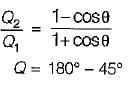
In case of semi-circular vanes, thb theoretical maximum efficiency of the wheel can be- a)50%
- b)67%
- c)75%
- d)100%
Correct answer is option 'D'. Can you explain this answer?
In case of semi-circular vanes, thb theoretical maximum efficiency of the wheel can be
a)
50%
b)
67%
c)
75%
d)
100%
|
|
Sanvi Kapoor answered |
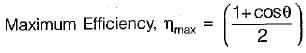
For θ = 0°, the curved vanes will become semicircular and ηmax = 1 or 100%.
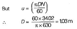
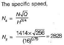
 = 4.43) What is the diameter of the impeller?
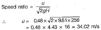
Consider the following statements:
1. Specific speed uniquely determines the type, shape and design of the turbine.
2. Both unit speed ‘n11’ and unit discharge ‘Q11’ are necessary to uniquely determine the type and design of the turbine.
Which of these statements is/are correct in respect of a hydraulic turbine?- a)2 alone
- b)1 alone
- c)Both 1 and 2
- d)Neither 1 nor 2
Correct answer is option 'B'. Can you explain this answer?
Consider the following statements:
1. Specific speed uniquely determines the type, shape and design of the turbine.
2. Both unit speed ‘n11’ and unit discharge ‘Q11’ are necessary to uniquely determine the type and design of the turbine.
Which of these statements is/are correct in respect of a hydraulic turbine?
1. Specific speed uniquely determines the type, shape and design of the turbine.
2. Both unit speed ‘n11’ and unit discharge ‘Q11’ are necessary to uniquely determine the type and design of the turbine.
Which of these statements is/are correct in respect of a hydraulic turbine?
a)
2 alone
b)
1 alone
c)
Both 1 and 2
d)
Neither 1 nor 2
|
|
Shalini Deshpande answered |
And specific speed are used to determine the performance of a turbine.
3. Specific speed is a dimensionless quantity that characterizes the geometry and performance of a turbine.
Which of the statements are true?
1. Specific speed uniquely determines the type, shape, and design of the turbine.
3. Specific speed is a dimensionless quantity that characterizes the geometry and performance of a turbine.
Statement 1 is true. Specific speed is a parameter that is used to classify and determine the type, shape, and design of a turbine. It gives an indication of the turbine's operating range and is used in selecting the appropriate turbine for a given application.
Statement 2 is false. Unit speed is not used to determine the performance of a turbine. Instead, specific speed is used for this purpose.
Statement 3 is true. Specific speed is a dimensionless quantity that is calculated using the rotational speed, flow rate, and head (or pressure difference) of a turbine. It characterizes the geometry and performance of the turbine and is used for comparing different turbine designs.
3. Specific speed is a dimensionless quantity that characterizes the geometry and performance of a turbine.
Which of the statements are true?
1. Specific speed uniquely determines the type, shape, and design of the turbine.
3. Specific speed is a dimensionless quantity that characterizes the geometry and performance of a turbine.
Statement 1 is true. Specific speed is a parameter that is used to classify and determine the type, shape, and design of a turbine. It gives an indication of the turbine's operating range and is used in selecting the appropriate turbine for a given application.
Statement 2 is false. Unit speed is not used to determine the performance of a turbine. Instead, specific speed is used for this purpose.
Statement 3 is true. Specific speed is a dimensionless quantity that is calculated using the rotational speed, flow rate, and head (or pressure difference) of a turbine. It characterizes the geometry and performance of the turbine and is used for comparing different turbine designs.
The cavitation and pitting can be prevented by creating which one of the following conditions? .- a)Reducing the pressure head
- b)Reducing the velocity head
- c)Increasing the elevation head
- d)Reducing the piezometric head
Correct answer is option 'B'. Can you explain this answer?
The cavitation and pitting can be prevented by creating which one of the following conditions? .
a)
Reducing the pressure head
b)
Reducing the velocity head
c)
Increasing the elevation head
d)
Reducing the piezometric head
|
|
Shilpa Pillai answered |
Cavitation occurs due to pressure falling below vapour pressure. Reducing the velocity head will increase pressure head and cavitation can. be prevented.
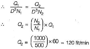
A centrifugal pump running at 500 rpm and at its maximum efficiency is delivering a head of 30 m at a flow rate of 60 liters per minute. If the rpm is changed to 1000, then the head H in metres and flow rate Q in litres per minute at maximum efficiency are estimated to be- a)H = 60, Q = 120
- b)H = 120, Q = 120
- c)H = 60, Q = 480
- d)H= 120, Q = 30
Correct answer is option 'B'. Can you explain this answer?
A centrifugal pump running at 500 rpm and at its maximum efficiency is delivering a head of 30 m at a flow rate of 60 liters per minute. If the rpm is changed to 1000, then the head H in metres and flow rate Q in litres per minute at maximum efficiency are estimated to be
a)
H = 60, Q = 120
b)
H = 120, Q = 120
c)
H = 60, Q = 480
d)
H= 120, Q = 30
|
|
Jyoti Choudhury answered |
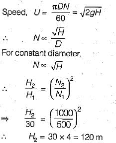
We also know that specific speed will be constant.
An impulse turbine- a)always operates submerged
- b)makes use of a draft tube
- c)operates by initial complete conversion to kinetic energy
- d)converts pressure head into velocity throughout the vanes
Correct answer is option 'C'. Can you explain this answer?
An impulse turbine
a)
always operates submerged
b)
makes use of a draft tube
c)
operates by initial complete conversion to kinetic energy
d)
converts pressure head into velocity throughout the vanes
|
|
Moumita Rane answered |
Impulse Turbine
A impulse turbine is a type of water turbine that operates by initially converting the potential energy of water into kinetic energy. It is commonly used in hydroelectric power plants and is known for its high efficiency and reliability.
Operating Submerged
Contrary to option (a), an impulse turbine does not always operate submerged. In fact, impulse turbines are designed to operate above the water level, with the water jet directed onto the turbine blades.
Draft Tube
Option (b) is incorrect as well. An impulse turbine does not make use of a draft tube. A draft tube is a component used in reaction turbines to recover the kinetic energy of water leaving the turbine and convert it back into pressure energy. Impulse turbines, on the other hand, do not require a draft tube as they operate based on the principle of converting the potential energy of water into kinetic energy.
Conversion to Kinetic Energy
The correct answer, option (c), states that an impulse turbine operates by initially converting the potential energy of water into kinetic energy. This is the fundamental principle behind the operation of an impulse turbine. The water enters the turbine through a nozzle, which accelerates the flow and increases its velocity. This high-velocity jet of water then strikes the turbine blades, causing them to rotate. The kinetic energy of the water is transferred to the turbine blades, resulting in mechanical work.
Pressure Head to Velocity Conversion
Option (d) is incorrect. While impulse turbines do convert pressure energy into kinetic energy, this conversion occurs in the nozzle, not throughout the vanes. The vanes of an impulse turbine are designed to efficiently capture the kinetic energy of the water jet and convert it into mechanical work, rather than further converting pressure energy into velocity.
In summary, an impulse turbine operates by initially converting the potential energy of water into kinetic energy. It does not always operate submerged, does not require a draft tube, and the conversion of pressure energy into velocity occurs in the nozzle, not throughout the vanes.
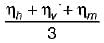
The overall efficiency of a Pelton turbine is 70%. If the mechanical efficiency is 85%, what is its hydraulic efficiency?- a)82.4%
- b)59.5%
- c)72.3%
- d)81.5%
Correct answer is option 'A'. Can you explain this answer?
The overall efficiency of a Pelton turbine is 70%. If the mechanical efficiency is 85%, what is its hydraulic efficiency?
a)
82.4%
b)
59.5%
c)
72.3%
d)
81.5%
|
|
Ameya Roy answered |
∴ hydraulic eff. = (0.70/0.85) x 100 = 82.4%
The function of an air vessel in a reciprocating pump is to obtain :- a)Reduction of suction head
- b)Rise in delivery head
- c)Continuous supply of water at uniform rate
- d)Increase in supply of water
Correct answer is option 'C'. Can you explain this answer?
The function of an air vessel in a reciprocating pump is to obtain :
a)
Reduction of suction head
b)
Rise in delivery head
c)
Continuous supply of water at uniform rate
d)
Increase in supply of water
|
|
Sravya Tiwari answered |
Air vessel ensure continuous supply of water at a uniform rate in a reciprocating pump. It results in saving of work against friction.
Percentage of work saved during stroke in
(i) single acting pump is 84.8%
(ii) double acting pump is 39.2%
The air vessels change the indicator diagram of the reciprocating pump.
Percentage of work saved during stroke in
(i) single acting pump is 84.8%
(ii) double acting pump is 39.2%
The air vessels change the indicator diagram of the reciprocating pump.
If the radius of the centrifugal pump impeller is reduced from 10 cm, the head developed by the pump will change from 10 m to- a)9 m of water
- b)8.1 m of water
- c)9.487 m of water
- d)11.111 m of water
Correct answer is option 'B'. Can you explain this answer?
If the radius of the centrifugal pump impeller is reduced from 10 cm, the head developed by the pump will change from 10 m to
a)
9 m of water
b)
8.1 m of water
c)
9.487 m of water
d)
11.111 m of water
|
|
Priyanka Shah answered |
 will remain same even when diameter is reduced.
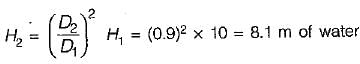
The specific speed of a turbine is defined as the speed of a Unit of such a size that it- a)delivers unit discharge at unit head
- b)delivers unit discharge at unit power
- c)produces unit power for unit head
- d)None of the above
Correct answer is option 'C'. Can you explain this answer?
The specific speed of a turbine is defined as the speed of a Unit of such a size that it
a)
delivers unit discharge at unit head
b)
delivers unit discharge at unit power
c)
produces unit power for unit head
d)
None of the above
|
|
Prem Prakash answered |
Specific speed of turbine refers that speed when turbine product unit power at given unit head
For 25 m or less available head which turbine will be suitable:- a)Pelton wheel
- b)Francis
- c)Kaplan
- d)None of the
Correct answer is option 'A'. Can you explain this answer?
For 25 m or less available head which turbine will be suitable:
a)
Pelton wheel
b)
Francis
c)
Kaplan
d)
None of the
|
|
Preethi Datta answered |
For low head of 1.5 to 20 metres Kaplan turbines and francis turbines are used.
For high head (> 25m) pelton wheel turbine is used.
For high head (> 25m) pelton wheel turbine is used.
Which one of the following statements is not correct in respect of hydraulic turbines?- a)(Speed) is proportional to (Diameter)1/2
- b)(Power) is proportional to (Speed)3
- c)(Power) is proportional to (Head)3/2
- d)(Speed) is proportional to (Head)1/2
Correct answer is option 'A'. Can you explain this answer?
Which one of the following statements is not correct in respect of hydraulic turbines?
a)
(Speed) is proportional to (Diameter)1/2
b)
(Power) is proportional to (Speed)3
c)
(Power) is proportional to (Head)3/2
d)
(Speed) is proportional to (Head)1/2
|
|
Gitanjali Menon answered |

Which one of the following statements is correct?- a)Reciprocating pumps are less efficient than centrifugal pumps.
- b)Delivery from a reciprocating pump is pulsating.
- c)Reciprocating pumps are suitable for large discharges and smaller heads.
- d)For a negative slip to occur, a reciprocating pump must have a coefficient of discharge less than unity.
Correct answer is option 'B'. Can you explain this answer?
Which one of the following statements is correct?
a)
Reciprocating pumps are less efficient than centrifugal pumps.
b)
Delivery from a reciprocating pump is pulsating.
c)
Reciprocating pumps are suitable for large discharges and smaller heads.
d)
For a negative slip to occur, a reciprocating pump must have a coefficient of discharge less than unity.
|
|
Abhay Kapoor answered |

If coefficient of discharge is more than one, negative slip would occur.
For a hydro-electric project with reaction turbine, the draft tube at the exit from the turbine is- a)always immersed in water
- b)always above the water
- c)may either be above or below the water
- d)above or below the water depending on the unit speed of the turbine
Correct answer is option 'A'. Can you explain this answer?
For a hydro-electric project with reaction turbine, the draft tube at the exit from the turbine is
a)
always immersed in water
b)
always above the water
c)
may either be above or below the water
d)
above or below the water depending on the unit speed of the turbine
|
|
Rajdeep Gupta answered |
Draft tube must be air-tight and under all-conditions of its operation its lower end must be submerged below the level of water in the tail race. It has two purposes:
(i) Permits a negative or suction head to be established at the runner exit.
(ii) Converts a large portion of velocity energy rejected from the runner into useful pressure energy.
(i) Permits a negative or suction head to be established at the runner exit.
(ii) Converts a large portion of velocity energy rejected from the runner into useful pressure energy.
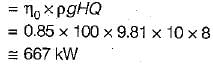
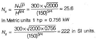
To generate 10,000 HP under a head of 81 m while working at a speed of 500 rpm, the turbine of choice would be- a)Peiton
- b)Kaplan
- c)Bulb
- d)Francis
Correct answer is option 'D'. Can you explain this answer?
To generate 10,000 HP under a head of 81 m while working at a speed of 500 rpm, the turbine of choice would be
a)
Peiton
b)
Kaplan
c)
Bulb
d)
Francis
|
|
Ananya Sharma answered |
Power developed in kW
= 10,000 x 0.756 = 7560 kW
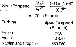
= 10,000 x 0.756 = 7560 kW
Tests were conducted on a francis turbine of 0.8 m diameter under a head of 9m. The turbine running at 240 rpm develops 84.5 kW and the water consumption was 1.2 m3/s. If the some turbine operated under a head of 16 m, the new discharge will be- a)1.4 m3/s
- b)1.6 m3/s
- c)1.8 m 3/s
- d)2 m3/s
Correct answer is option 'B'. Can you explain this answer?
Tests were conducted on a francis turbine of 0.8 m diameter under a head of 9m. The turbine running at 240 rpm develops 84.5 kW and the water consumption was 1.2 m3/s. If the some turbine operated under a head of 16 m, the new discharge will be
a)
1.4 m3/s
b)
1.6 m3/s
c)
1.8 m 3/s
d)
2 m3/s
|
|
Rounak Saini answered |
Given data:
Diameter of Francis turbine (D) = 0.8 m
Head (H1) = 9 m
Turbine speed (N1) = 240 rpm
Power developed (P1) = 84.5 kW
Water consumption (Q1) = 1.2 m^3/s
To find:
New discharge (Q2) when the turbine operates under a head of 16 m.
Formula:
The power developed by a Francis turbine is given by the equation:
P = ρ * g * Q * H * η
where,
P = Power developed (kW)
ρ = Density of water (1000 kg/m^3)
g = Acceleration due to gravity (9.81 m/s^2)
Q = Discharge (m^3/s)
H = Head (m)
η = Efficiency of the turbine
The specific speed (Ns) of a turbine is given by the equation:
Ns = N * √Q / √H
where,
Ns = Specific speed
N = Turbine speed (rpm)
The specific speed is constant for a turbine, so we can use it to find the new discharge.
Calculation:
1. Specific speed (Ns1) for the given turbine:
Ns1 = N1 * √Q1 / √H1
2. Specific speed (Ns2) for the turbine operating under a head of 16 m:
Ns2 = N1 * √Q2 / √H2
Since the specific speed is constant, we can equate Ns1 and Ns2:
Ns1 = Ns2
3. Substituting the values in the equation:
N1 * √Q1 / √H1 = N1 * √Q2 / √H2
4. Simplifying the equation:
√Q2 / √H2 = √Q1 / √H1
5. Cross-multiplying the equation:
√Q2 * √H1 = √Q1 * √H2
6. Squaring both sides of the equation:
Q2 * H1 = Q1 * H2
7. Solving for Q2:
Q2 = (Q1 * H2) / H1
8. Substituting the given values:
Q2 = (1.2 * 16) / 9
Q2 ≈ 2.133 m^3/s
Therefore, the new discharge (Q2) when the turbine operates under a head of 16 m is approximately 2.133 m^3/s.
Hence, the correct answer is option 'B' (1.6 m^3/s).
A centrifugal pump gives maximum efficiency when its impeller blades are- a)Bent forward
- b)Bent, backward
- c)Straight
- d)Wave-shaped
Correct answer is option 'B'. Can you explain this answer?
A centrifugal pump gives maximum efficiency when its impeller blades are
a)
Bent forward
b)
Bent, backward
c)
Straight
d)
Wave-shaped
|
|
Pranab Chaudhary answered |
**Explanation:**
**Centrifugal Pump:**
A centrifugal pump is a type of dynamic pump that uses a rotating impeller to increase the pressure and flow of a fluid. It is widely used in various industries for pumping liquids such as water, oil, and chemicals.
**Impeller Blades:**
The impeller is the rotating component of the centrifugal pump that transfers energy to the fluid. It consists of curved blades that are designed to increase the velocity of the fluid as it passes through the pump.
**Efficiency of a Centrifugal Pump:**
The efficiency of a centrifugal pump is a measure of how effectively it converts the input power into useful work. It is expressed as a percentage and is calculated by dividing the output power by the input power and multiplying by 100.
**Effect of Impeller Blade Shape on Efficiency:**
The shape of the impeller blades plays a significant role in determining the efficiency of a centrifugal pump. Different impeller blade shapes can result in different flow patterns and hydraulic losses, which ultimately affect the overall efficiency of the pump.
**Explanation of Option 'B': Bent, backward:**
Option 'B' states that the impeller blades should be bent backward to achieve maximum efficiency. This means that the blades should be curved in the opposite direction of the rotation of the impeller.
**Reasoning behind Option 'B':**
When the impeller blades are bent backward, it creates a higher pressure on the backside of the blade and a lower pressure on the front side. This pressure difference helps to push the fluid in the desired direction and increases the efficiency of the pump. Additionally, the backward bend of the blades helps to reduce the hydraulic losses and recirculation within the pump, further enhancing its efficiency.
**Advantages of Bent, Backward Impeller Blades:**
1. Increased Pressure Difference: The backward bend of the blades creates a higher pressure on the backside, which helps to push the fluid forward more effectively.
2. Reduced Hydraulic Losses: The backward bend helps to minimize the hydraulic losses and recirculation within the pump, resulting in improved efficiency.
3. Better Flow Control: The backward bend of the blades allows for better flow control and reduces the risk of cavitation.
Overall, the bent, backward impeller blades provide better performance and efficiency in a centrifugal pump compared to other blade shapes.
Cavitation in fluid flow occurs when- a)The total energy suddenly increases
- b)The total energy suddenly decreases
- c)The velocity head reduces to zero
- d)The pressure of flow decreases to a value close to its vapour pressure
Correct answer is option 'D'. Can you explain this answer?
Cavitation in fluid flow occurs when
a)
The total energy suddenly increases
b)
The total energy suddenly decreases
c)
The velocity head reduces to zero
d)
The pressure of flow decreases to a value close to its vapour pressure

|
Kiran Gupta answered |
Cavitation in fluid flow occurs when the pressure of the flow decreases to a value close to its vapor pressure. This phenomenon is characterized by the formation and subsequent collapse of vapor-filled cavities or bubbles in the fluid. Cavitation can have detrimental effects on fluid flow systems, causing damage to equipment and reducing overall system efficiency.
Explanation:
1. Introduction to Cavitation:
Cavitation is a complex phenomenon that occurs in fluid flow when the pressure drops below the vapor pressure of the fluid. It can occur in various fluid systems, including pumps, turbines, propellers, and pipes. When the pressure drops to a critical value, the fluid undergoes a phase change from a liquid to a vapor, forming vapor-filled cavities or bubbles.
2. Vapor Pressure:
Vapor pressure is the pressure exerted by the vapor phase of a substance in equilibrium with its liquid phase at a given temperature. It represents the tendency of the liquid to evaporate or transition to a vapor state. When the pressure of the fluid drops to a value close to its vapor pressure, the fluid starts to vaporize, leading to the formation of vapor-filled cavities.
3. Formation of Cavities:
As the pressure decreases, the fluid starts to vaporize, forming small vapor-filled cavities or bubbles. These cavities are typically formed in regions of high flow velocity or areas with significant pressure drops, such as around sharp edges or in narrow channels. The formation of cavities is a dynamic process, with the cavities growing and collapsing as the flow continues.
4. Cavitation Effects:
The collapse of vapor-filled cavities or bubbles can have detrimental effects on fluid flow systems. When the cavities collapse, they create shock waves and high-pressure regions, leading to localized erosion and damage to the system components. This erosion can result in the degradation of equipment, reduced system efficiency, and increased maintenance costs.
5. Prevention and Control:
To prevent or control cavitation, various measures can be implemented. These include increasing the pressure of the fluid, reducing flow velocities, smoothing flow passages, and using materials resistant to cavitation erosion. Additionally, the design of fluid flow systems should consider the potential for cavitation and incorporate features to mitigate its effects.
In conclusion, cavitation in fluid flow occurs when the pressure of the flow decreases to a value close to its vapor pressure. The formation and collapse of vapor-filled cavities or bubbles can have detrimental effects on fluid flow systems, leading to damage and reduced efficiency. Understanding and mitigating cavitation is crucial in designing and operating fluid flow systems effectively.
A hydraulic turbine has a discharge of 5 m3/sec, when operating under a head of 20 m with a speed of 500 rpm, If it is to operate under a head of 15 m, for the same discharge, the rotational speed in rpm will approximately be
- a)403
- b)433
- c)627
- d)388
Correct answer is option 'B'. Can you explain this answer?
A hydraulic turbine has a discharge of 5 m3/sec, when operating under a head of 20 m with a speed of 500 rpm, If it is to operate under a head of 15 m, for the same discharge, the rotational speed in rpm will approximately be
a)
403
b)
433
c)
627
d)
388
|
|
Ananya Sharma answered |
Given:
Discharge, Q = 5 m3/sec
Head, H1 = 20 m
Speed, N1 = 500 rpm
Head, H2 = 15 m
We have to find the rotational speed of the turbine for H2.
Formula used:
Speed of the turbine, N ∝ (H)½
Calculation:
From the given data, we can write:
N1/√H1 = N2/√H2
500/√20 = N2/√15
N2 = 500 × √(15/20)
N2 = 500 × √0.75
N2 = 500 × 0.866
N2 = 433 rpm
Therefore, the rotational speed of the turbine for H2 is approximately 433 rpm, and the correct option is (b).
If two pumps identical in all aspects and each capable of delivering a discharge Q against a head H are connected- a)In parallel, the resulting d is charge is G against a head of 2 H
- b)In series, the resulting d is charge is 2G against a head of 2 H
- c)In series, the resulting d is charge is 2G against a head of H
- d)In parallel, the resulting d is charge is 2G against a head H
Correct answer is option 'D'. Can you explain this answer?
If two pumps identical in all aspects and each capable of delivering a discharge Q against a head H are connected
a)
In parallel, the resulting d is charge is G against a head of 2 H
b)
In series, the resulting d is charge is 2G against a head of 2 H
c)
In series, the resulting d is charge is 2G against a head of H
d)
In parallel, the resulting d is charge is 2G against a head H

|
Aditya Majumdar answered |
Understanding Pump Configurations
When dealing with pumps, their configuration significantly influences the system's performance. Let's explore the two configurations: parallel and series.
Pumps in Parallel
- Configuration: Two identical pumps are connected side by side.
- Flow Rate: When pumps operate in parallel, the flow rates add up while the head remains constant.
- Resulting Discharge: Therefore, if each pump can deliver a discharge Q, the total discharge (G) becomes:
- G = Q + Q = 2Q
- Head: The head remains at H, as both pumps provide the same lift.
Pumps in Series
- Configuration: Two identical pumps are connected in a sequence.
- Flow Rate: In this setup, the flow rate remains the same while the heads add up.
- Resulting Discharge: Thus, if each pump can deliver a discharge Q, the total discharge (G) remains:
- G = Q (not doubled)
- Head: The total head becomes 2H, as both pumps contribute to the lift.
Correct Answer Explanation
The correct answer is option 'D' for the following reasons:
- In Parallel Configuration: The flow capacities of the two pumps add up, resulting in a total discharge of 2G against a head of H.
- Implication: This means that while you benefit from an increased flow rate, the head remains constant, making it suitable for scenarios where greater volume delivery is needed without increasing lift.
By understanding how pumps function in different configurations, you can optimize your system for specific requirements.
A high efficiency pump is required for low discharge, high head and low maintenance cost. Delivery of water need not be continuous. The pump need not run at high speed. Which one of the following is the correct choice?- a)Centrifugal pump
- b)Reciprocating pump
- c)Air lift pump
- d)Hydraulic ram
Correct answer is option 'B'. Can you explain this answer?
A high efficiency pump is required for low discharge, high head and low maintenance cost. Delivery of water need not be continuous. The pump need not run at high speed. Which one of the following is the correct choice?
a)
Centrifugal pump
b)
Reciprocating pump
c)
Air lift pump
d)
Hydraulic ram
|
|
Kiran Gupta answered |
Reciprocating pump
Reciprocating pumps are positive displacement pumps that use a piston or plunger to move fluid. They are often the preferred choice for applications requiring low discharge, high head, and low maintenance cost. Here's why they are the correct choice in this scenario:
Low discharge:
- Reciprocating pumps are capable of providing low discharge rates because they operate by displacing a fixed volume of fluid with each stroke of the piston or plunger. This allows for precise control over the flow rate, making it suitable for applications that require low discharge.
High head:
- Reciprocating pumps can generate high head pressures due to their positive displacement nature. As the piston or plunger moves, it creates a high-pressure zone that forces the fluid to move against the resistance provided by the system. This makes them ideal for pumping fluids to higher elevations or overcoming significant friction losses.
Low maintenance cost:
- Reciprocating pumps are known for their simplicity and robustness, resulting in lower maintenance costs compared to other pump types. They have fewer moving parts, reducing the chances of mechanical failure. Additionally, their design allows for easy access and inspection of components, simplifying maintenance and repair tasks.
Non-continuous delivery:
- Reciprocating pumps can handle non-continuous delivery requirements effectively. They can start and stop rapidly without causing any damage to the pump or affecting its performance. This flexibility makes them suitable for applications where water delivery does not need to be continuous.
Low speed operation:
- Reciprocating pumps can operate at lower speeds compared to centrifugal pumps, which require higher rotational speeds to generate sufficient head and flow. The lower speed operation reduces wear and tear on the pump components, resulting in extended equipment life and lower maintenance costs.
Overall, a reciprocating pump is the correct choice for the given requirements of low discharge, high head, low maintenance cost, non-continuous delivery, and low-speed operation. It provides the necessary features and characteristics to meet these requirements effectively.
Which one of the following statements is correct?- a)Pumps operating in series boost the discharge whereas pumps operating in parallel boost the head.
- b)Pumps operating in parallel boost the discharge whereas pumps operating in series boost the head.
- c)In both the above cases there would be a boost in discharge only.
- d)In both the above cases there would be a boost in head only.
Correct answer is option 'B'. Can you explain this answer?
Which one of the following statements is correct?
a)
Pumps operating in series boost the discharge whereas pumps operating in parallel boost the head.
b)
Pumps operating in parallel boost the discharge whereas pumps operating in series boost the head.
c)
In both the above cases there would be a boost in discharge only.
d)
In both the above cases there would be a boost in head only.
|
|
Navya Kaur answered |
Explanation:
Operating in Series vs. Operating in Parallel:
When pumps are operating in series, they are connected one after the other so that the discharge is the same across each pump. On the other hand, when pumps are operating in parallel, they are connected side by side so that the total discharge is the sum of the discharge of each pump.
Effect on Discharge and Head:
- Pumps operating in parallel boost the discharge because each pump adds to the total flow rate.
- Pumps operating in series boost the head because the total head is the sum of the heads produced by each pump.
Correct Statement:
- The correct statement is that pumps operating in parallel boost the discharge whereas pumps operating in series boost the head. This is because when pumps are in parallel, the flow rates add up, increasing the overall discharge. Conversely, when pumps are in series, the heads add up, resulting in a higher total head.
Rotodyn a micpumps a reclassified as
1. centrifugal pumps
2. screw pumps
3. propeller pumps
Which of these statements are correct?- a)Both 1 and 2
- b)Both 1 and 3
- c)Both 2 and 3
- d)1, 2 and 3
Correct answer is option 'B'. Can you explain this answer?
Rotodyn a micpumps a reclassified as
1. centrifugal pumps
2. screw pumps
3. propeller pumps
Which of these statements are correct?
1. centrifugal pumps
2. screw pumps
3. propeller pumps
Which of these statements are correct?
a)
Both 1 and 2
b)
Both 1 and 3
c)
Both 2 and 3
d)
1, 2 and 3
|
|
Debolina Chavan answered |
The correct answer is option 'B' - Both 1 and 3.
Centrifugal pumps and propeller pumps are both types of rotodynamic pumps. Let's discuss each type in detail to understand why this answer is correct.
1. Centrifugal pumps:
Centrifugal pumps are the most commonly used type of rotodynamic pump. They work on the principle of centrifugal force, which is generated by the rotation of an impeller. The impeller has curved blades that rotate rapidly, creating a high-velocity flow of liquid. This high-velocity flow is then converted into pressure, which allows the pump to move the liquid from one location to another. Centrifugal pumps are widely used in various applications, including water supply systems, sewage treatment plants, and industrial processes.
2. Screw pumps:
Screw pumps, also known as rotary pumps, are not classified as rotodynamic pumps. They belong to the positive displacement pump category. Unlike centrifugal pumps, screw pumps use rotating screws or gears to move the liquid. The rotating screws or gears create a vacuum, which allows the liquid to be drawn into the pump and then pushed out through the discharge port. Screw pumps are known for their ability to handle viscous fluids and are commonly used in applications such as oil refineries, chemical processing plants, and food processing industries.
3. Propeller pumps:
Propeller pumps are another type of rotodynamic pump. They are specifically designed to handle large volumes of water with low to moderate heads. Similar to centrifugal pumps, propeller pumps use an impeller to generate a high-velocity flow of liquid. However, the impeller of a propeller pump is typically axial flow, meaning the flow moves parallel to the axis of the impeller. This design allows the pump to efficiently move large volumes of water, making it suitable for applications such as irrigation, flood control, and drainage systems.
In summary, both centrifugal pumps and propeller pumps are types of rotodynamic pumps. Screw pumps, on the other hand, belong to the positive displacement pump category and are not classified as rotodynamic pumps. Therefore, the correct answer is option 'B' - Both 1 and 3.
The efficiency of a centrifugal pump is expressed in terms of
1. manometer efficiency
2. volumetric efficiency
3. mechanical efficiency
4. overall efficiency
Which of these statements are correct?- a)1, 2 and 4
- b)2, 3 and 4
- c)Both 3 and 4
- d)1, 2, 3 and 4
Correct answer is option 'C'. Can you explain this answer?
The efficiency of a centrifugal pump is expressed in terms of
1. manometer efficiency
2. volumetric efficiency
3. mechanical efficiency
4. overall efficiency
Which of these statements are correct?
1. manometer efficiency
2. volumetric efficiency
3. mechanical efficiency
4. overall efficiency
Which of these statements are correct?
a)
1, 2 and 4
b)
2, 3 and 4
c)
Both 3 and 4
d)
1, 2, 3 and 4
|
|
Srestha Datta answered |
Centrifugal pumps are widely used in various industries for fluid transportation. The efficiency of a centrifugal pump is an important parameter to determine its performance. It is expressed in terms of various efficiencies, including manometer efficiency, volumetric efficiency, mechanical efficiency, and overall efficiency.
1. Manometer Efficiency:
- Manometer efficiency refers to the ratio of the head developed by the pump to the head measured by a manometer.
- It takes into account the energy losses due to fluid friction in the impeller and volute casing.
- Manometer efficiency is given by the equation: Manometer efficiency = (Head developed by the pump / Head measured by the manometer) * 100%.
2. Volumetric Efficiency:
- Volumetric efficiency is the ratio of the actual volume of fluid delivered by the pump to the theoretical volume that should be delivered.
- It takes into consideration the leakage losses and slip of the fluid within the pump.
- Volumetric efficiency is given by the equation: Volumetric efficiency = (Actual volume of fluid delivered / Theoretical volume of fluid to be delivered) * 100%.
3. Mechanical Efficiency:
- Mechanical efficiency is the ratio of the power output delivered by the pump to the power input required to drive the pump.
- It takes into account the losses due to mechanical friction and inefficiencies in the pump's internal components.
- Mechanical efficiency is given by the equation: Mechanical efficiency = (Power output / Power input) * 100%.
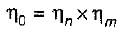
4. Overall Efficiency:
- Overall efficiency is the product of manometer efficiency, volumetric efficiency, and mechanical efficiency.
- It represents the overall performance of the centrifugal pump, taking into account all the losses and inefficiencies.
- Overall efficiency is given by the equation: Overall efficiency = (Manometer efficiency / 100) * (Volumetric efficiency / 100) * (Mechanical efficiency / 100).
Therefore, the correct statements are:
c) Both 3 and 4
- Mechanical efficiency and overall efficiency are correct statements as they are widely used to evaluate the performance of a centrifugal pump.
1. Manometer Efficiency:
- Manometer efficiency refers to the ratio of the head developed by the pump to the head measured by a manometer.
- It takes into account the energy losses due to fluid friction in the impeller and volute casing.
- Manometer efficiency is given by the equation: Manometer efficiency = (Head developed by the pump / Head measured by the manometer) * 100%.
2. Volumetric Efficiency:
- Volumetric efficiency is the ratio of the actual volume of fluid delivered by the pump to the theoretical volume that should be delivered.
- It takes into consideration the leakage losses and slip of the fluid within the pump.
- Volumetric efficiency is given by the equation: Volumetric efficiency = (Actual volume of fluid delivered / Theoretical volume of fluid to be delivered) * 100%.
3. Mechanical Efficiency:
- Mechanical efficiency is the ratio of the power output delivered by the pump to the power input required to drive the pump.
- It takes into account the losses due to mechanical friction and inefficiencies in the pump's internal components.
- Mechanical efficiency is given by the equation: Mechanical efficiency = (Power output / Power input) * 100%.
4. Overall Efficiency:
- Overall efficiency is the product of manometer efficiency, volumetric efficiency, and mechanical efficiency.
- It represents the overall performance of the centrifugal pump, taking into account all the losses and inefficiencies.
- Overall efficiency is given by the equation: Overall efficiency = (Manometer efficiency / 100) * (Volumetric efficiency / 100) * (Mechanical efficiency / 100).
Therefore, the correct statements are:
c) Both 3 and 4
- Mechanical efficiency and overall efficiency are correct statements as they are widely used to evaluate the performance of a centrifugal pump.


Chapter doubts & questions for Hydraulic Machines: Turbines & Pumps - Fluid Mechanics for Mechanical Engineering 2025 is part of Mechanical Engineering exam preparation. The chapters have been prepared according to the Mechanical Engineering exam syllabus. The Chapter doubts & questions, notes, tests & MCQs are made for Mechanical Engineering 2025 Exam. Find important definitions, questions, notes, meanings, examples, exercises, MCQs and online tests here.
Chapter doubts & questions of Hydraulic Machines: Turbines & Pumps - Fluid Mechanics for Mechanical Engineering in English & Hindi are available as part of Mechanical Engineering exam.
Download more important topics, notes, lectures and mock test series for Mechanical Engineering Exam by signing up for free.
Fluid Mechanics for Mechanical Engineering
56 videos|154 docs|75 tests
|
|
© EduRev
|
Education Revolution
|


|


Signup on EduRev and stay on top of your study goals
10M+ students crushing their study goals daily