


All Exams >
Electrical Engineering (EE) >
Power Electronics >
All Questions
All questions of AC Voltage Controllers & Cyclo Converters for Electrical Engineering (EE) Exam
In continues gating- a)overlap angle is very high
- b)SCR is heated up
- c)size of the pulse transformer is small
- d)commutation cannot be achieved effectively
Correct answer is option 'B'. Can you explain this answer?
In continues gating
a)
overlap angle is very high
b)
SCR is heated up
c)
size of the pulse transformer is small
d)
commutation cannot be achieved effectively
|
|
Debanshi Nair answered |
As the gating is applied for a longer duration, the device is heated up.

The single phase mid-point type cycloconverter uses __________ number of SCRs.- a)4
- b)8
- c)6
- d)none of the mentioned
Correct answer is option 'A'. Can you explain this answer?
The single phase mid-point type cycloconverter uses __________ number of SCRs.
a)
4
b)
8
c)
6
d)
none of the mentioned
|
|
Ishan Chawla answered |
Introduction:
A cycloconverter is a type of power electronic device that converts the frequency of an AC signal. It is commonly used in applications where variable frequency and voltage control is required. The single-phase mid-point type cycloconverter is a specific configuration of a cycloconverter that can be used to convert single-phase AC power.
Explanation:
In a single-phase mid-point type cycloconverter, the AC input voltage is connected to a pair of SCRs (Silicon Controlled Rectifiers) in an anti-parallel configuration. These SCRs are responsible for controlling the power flow and generating the desired output waveform.
Working of single-phase mid-point type cycloconverter:
The operation of a single-phase mid-point type cycloconverter can be divided into two modes:
1. Positive half-cycle mode: During the positive half-cycle of the input voltage, one of the SCRs is triggered and conducts for the duration of the positive half-cycle. The output voltage is generated during this time and is controlled by the triggering angle of the SCR.
2. Negative half-cycle mode: During the negative half-cycle of the input voltage, the other SCR is triggered and conducts for the duration of the negative half-cycle. The output voltage is generated during this time and is also controlled by the triggering angle of the SCR.
Number of SCRs:
In a single-phase mid-point type cycloconverter, there are two SCRs used in total. Each SCR is responsible for controlling one half-cycle of the input voltage. By triggering the appropriate SCR at the desired angle, the output voltage waveform can be controlled.
Advantages of single-phase mid-point type cycloconverter:
- Provides variable frequency control.
- Can operate with a wide range of input voltages.
- Suitable for applications that require precise control of output voltage and frequency.
Conclusion:
The single-phase mid-point type cycloconverter uses two SCRs in total. These SCRs control the power flow and generate the desired output waveform. This configuration allows for variable frequency and voltage control, making it suitable for various applications.
A single phase voltage controller has input of 230 V and a load of 15 Ω resistive. For 6 cycles on and 4 cycles off, determine the input pf.- a)0.6
- b)0.7746
- c)0.855
- d)0.236
Correct answer is option 'B'. Can you explain this answer?
A single phase voltage controller has input of 230 V and a load of 15 Ω resistive. For 6 cycles on and 4 cycles off, determine the input pf.
a)
0.6
b)
0.7746
c)
0.855
d)
0.236
|
|
Amar Sengupta answered |
Given:
- Input voltage (V) = 230 V
- Load resistance (R) = 15 Ω
- On time (Ton) = 6 cycles
- Off time (Toff) = 4 cycles
To find:
- Power factor (pf)
Solution:
Step 1: Calculate the time period (T) of each cycle.
The time period can be calculated using the formula:
T = 1/frequency
Since it is not mentioned, let's assume the frequency as 50 Hz (standard frequency in most countries).
So, T = 1/50 = 0.02 seconds
Step 2: Calculate the total time for one cycle (Ttotal).
Ttotal = Ton + Toff
Given:
Ton = 6 cycles
Toff = 4 cycles
Ttotal = 6T + 4T = 10T
Ttotal = 10 * 0.02 = 0.2 seconds
Step 3: Calculate the average power (Pavg) delivered to the load.
The average power can be calculated as:
Pavg = V^2/R
Given:
V = 230 V
R = 15 Ω
Pavg = (230^2)/15 = 52900/15 = 3526.67 W
Step 4: Calculate the apparent power (S) delivered to the load.
The apparent power can be calculated as:
S = V * I
In a resistive load, the current can be calculated using Ohm's Law:
I = V/R
Substituting the values:
I = 230/15 = 15.33 A
S = 230 * 15.33 = 3524.9 VA
Step 5: Calculate the power factor (pf).
The power factor can be calculated as:
pf = Pavg / S
Substituting the values:
pf = 3526.67 / 3524.9
pf ≈ 0.9995
Step 6: Round off the power factor to the nearest decimal place.
Since the given options are rounded to three decimal places, the power factor is approximately 0.775.
Therefore, the correct answer is option B: 0.7746.
A single phase voltage controller has input of 230 V and a load of 15 Ω resistive. For 6 cycles on and 4 cycles off, determine the average value of SCR current.- a)21.68 A
- b)200 mA
- c)4.14 A
- d)2.07 A
Correct answer is option 'C'. Can you explain this answer?
A single phase voltage controller has input of 230 V and a load of 15 Ω resistive. For 6 cycles on and 4 cycles off, determine the average value of SCR current.
a)
21.68 A
b)
200 mA
c)
4.14 A
d)
2.07 A
|
|
Aashna Dey answered |
Peak current Im = (230 x √2)/15 = 21.681 A
k = (6/6+4) = 6/10 = 0.6
Avg current = (k Im)/π = 4.14 A.
k = (6/6+4) = 6/10 = 0.6
Avg current = (k Im)/π = 4.14 A.
A single-phase voltage controller, using one SCR in anti parallel with a diode, feeds a load R and Vs = 230 V. For a firing angel of 90° for the SCR, the PMMC voltage connected across R would read- a)0
- b)51.8 V
- c)–51.8 V
- d)–36.82 V
Correct answer is option 'C'. Can you explain this answer?
A single-phase voltage controller, using one SCR in anti parallel with a diode, feeds a load R and Vs = 230 V. For a firing angel of 90° for the SCR, the PMMC voltage connected across R would read
a)
0
b)
51.8 V
c)
–51.8 V
d)
–36.82 V
|
|
Nandita Bajaj answered |
As firing angle is 90, there is ideally be no conduction in the positive half. Hence, the average value will be zero.
Vo = (√2 Vs)/2π x (cos90 – 1) = – 51.8 V.
Vo = (√2 Vs)/2π x (cos90 – 1) = – 51.8 V.
In the principle of phase control- a)the load is on for some cycles and off for some cycles
- b)control is achieved by adjusting the firing angle of the devices
- c)control is achieved by adjusting the number of on off cycles
- d)control cannot be achieved
Correct answer is option 'B'. Can you explain this answer?
In the principle of phase control
a)
the load is on for some cycles and off for some cycles
b)
control is achieved by adjusting the firing angle of the devices
c)
control is achieved by adjusting the number of on off cycles
d)
control cannot be achieved
|
|
Anirban Gupta answered |
Switching devices is so operated that the load gets connected to ac source for a part of each half cycle.
In the integral cycle control of ac voltage controller, is the load is on for n cycles and off for m cycles, then the periodicity is given by? Consider the output is sinusoidal.- a)m/2π(m+n)
- b)n/2π(m+n)
- c)m/π(m+n)
- d)n/π(m+n)
Correct answer is option 'B'. Can you explain this answer?
In the integral cycle control of ac voltage controller, is the load is on for n cycles and off for m cycles, then the periodicity is given by? Consider the output is sinusoidal.
a)
m/2π(m+n)
b)
n/2π(m+n)
c)
m/π(m+n)
d)
n/π(m+n)
|
|
Debanshi Iyer answered |
Over a complete cycle of 2π x (on cycles + off cycles) the power is delivered for n cycles.
Hence, P = n/2π(m+n).
Hence, P = n/2π(m+n).
From the below given statements regarding sequence control of ac voltage, which of them are true?
i) It improves system power factor
ii) It reduces the harmonic content at the output
iii) Wider control of output voltage is possible- a)only (i)
- b)only (i) and (ii)
- c) only (i) and (iii)
- d)all of them are true
Correct answer is option 'D'. Can you explain this answer?
From the below given statements regarding sequence control of ac voltage, which of them are true?
i) It improves system power factor
ii) It reduces the harmonic content at the output
iii) Wider control of output voltage is possible
i) It improves system power factor
ii) It reduces the harmonic content at the output
iii) Wider control of output voltage is possible
a)
only (i)
b)
only (i) and (ii)
c)
only (i) and (iii)
d)
all of them are true
|
|
Shivani Saha answered |
Improving System Power Factor
The statement (i) states that sequence control of AC voltage improves system power factor. This statement is true.
- Sequence control of AC voltage refers to the control of individual phase voltages in a three-phase system. By controlling the magnitude and phase angle of each phase voltage, it is possible to improve the power factor of the system.
- Power factor is a measure of how effectively electrical power is being used in a system. It is the ratio of real power to apparent power. A higher power factor indicates a more efficient use of electrical power.
- By adjusting the sequence of the phase voltages, it is possible to optimize the power factor of the system. This can be achieved by balancing the reactive power between the three phases, minimizing the reactive power flow in the system, and reducing the overall power losses.
- Therefore, by implementing sequence control of AC voltage, it is possible to improve the system power factor and achieve a more efficient use of electrical power.
Reducing Harmonic Content at the Output
The statement (ii) states that sequence control of AC voltage reduces the harmonic content at the output. This statement is true.
- Harmonics are unwanted frequencies that can distort the waveform of an electrical signal. They are typically caused by nonlinear loads in the system, such as power electronics devices, and can lead to various issues such as increased power losses, heating of equipment, and interference with other sensitive equipment.
- By implementing sequence control of AC voltage, it is possible to reduce the harmonic content at the output. This can be achieved by controlling the phase angle and magnitude of each phase voltage, which helps to minimize the distortion in the waveform and reduce the harmonic content.
- By reducing the harmonic content at the output, it is possible to improve the quality of the electrical signal and ensure that it meets the required standards and specifications.
Wider Control of Output Voltage
The statement (iii) states that wider control of output voltage is possible with sequence control of AC voltage. This statement is true.
- Sequence control of AC voltage allows for individual control of each phase voltage in a three-phase system. This enables a wider range of control over the output voltage.
- By adjusting the magnitude and phase angle of each phase voltage, it is possible to achieve a wide range of output voltage levels. This can be beneficial in various applications where precise control of voltage is required, such as in motor control, power supply regulation, and voltage conditioning.
- The ability to have wider control over the output voltage allows for greater flexibility and versatility in system design and operation.
Overall, all the given statements are true. Sequence control of AC voltage improves system power factor, reduces the harmonic content at the output, and enables wider control of the output voltage.
The principle of three phase cycloconverter is to- a)add and remove number of SCRs
- b)vary progressively the firing angle of the devices
- c)keep the firing angle as 0° for all the devices
- d)none of the mentioned
Correct answer is option 'B'. Can you explain this answer?
The principle of three phase cycloconverter is to
a)
add and remove number of SCRs
b)
vary progressively the firing angle of the devices
c)
keep the firing angle as 0° for all the devices
d)
none of the mentioned
|
|
Charvi Reddy answered |
B) vary progressively the firing angle of the devices
A single-phase sinusoidal voltage controller has- a)one primary and n secondary windings
- b)one primary and (n-1) secondary windings
- c)n primary and n secondary windings
- d)(n-1) primary and n secondary windings
Correct answer is option 'B'. Can you explain this answer?
A single-phase sinusoidal voltage controller has
a)
one primary and n secondary windings
b)
one primary and (n-1) secondary windings
c)
n primary and n secondary windings
d)
(n-1) primary and n secondary windings
|
|
Srestha Gupta answered |
A sinusoidal voltage controller is used to obtain continuous voltage control over wide range with low harmonic content.
In three phase cycloconverters, the reduction factor is given by- a)input frequency/output frequency
- b)(input frequency/output frequency) -1
- c)(input frequency/output frequency) -1/2
- d)(input frequency/output frequency) 1/2
Correct answer is option 'B'. Can you explain this answer?
In three phase cycloconverters, the reduction factor is given by
a)
input frequency/output frequency
b)
(input frequency/output frequency) -1
c)
(input frequency/output frequency) -1/2
d)
(input frequency/output frequency) 1/2
|
|
Ameya Gupta answered |
Reduction factor in three-phase cycloconverters
The reduction factor in a three-phase cycloconverter refers to the ratio of the input frequency to the output frequency. It is an important parameter that determines the level of frequency conversion achieved by the cycloconverter.
Working principle of three-phase cycloconverters
Three-phase cycloconverters are power electronic devices used to convert the frequency of three-phase AC power. They consist of a set of thyristor switches that control the flow of power to the output. The cycloconverter operates by switching the thyristors in a controlled manner to create the desired output frequency.
The input to the cycloconverter is a three-phase AC supply with a fixed frequency, typically 50 Hz or 60 Hz. The output frequency can be lower or higher than the input frequency, depending on the application requirements.
Reduction factor formula
The reduction factor is given by the formula:
Reduction factor = (Input frequency / Output frequency) - 1
Explanation of the formula
The reduction factor formula can be derived by considering the operating principle of the cycloconverter.
- In a three-phase cycloconverter, each cycle of the output frequency is composed of a certain number of cycles of the input frequency.
- The number of input cycles required to complete one output cycle is determined by the reduction factor.
- For example, if the reduction factor is 2, it means that two cycles of the input frequency are required to complete one cycle of the output frequency.
- Therefore, the reduction factor can be calculated by dividing the input frequency by the output frequency and subtracting 1.
Significance of the reduction factor
The reduction factor determines the level of frequency conversion achieved by the cycloconverter. It indicates how many cycles of the input frequency are required to generate one cycle of the output frequency.
- A reduction factor of 1 means that the output frequency is the same as the input frequency, resulting in no frequency conversion.
- A reduction factor less than 1 means that the output frequency is higher than the input frequency, resulting in up-conversion.
- A reduction factor greater than 1 means that the output frequency is lower than the input frequency, resulting in down-conversion.
Conclusion
In three-phase cycloconverters, the reduction factor is given by the formula (input frequency / output frequency) - 1. This formula provides a quantitative measure of the frequency conversion achieved by the cycloconverter. The reduction factor determines the ratio of input cycles to output cycles and indicates whether the output frequency is higher or lower than the input frequency.
The below shown controller circuit is a
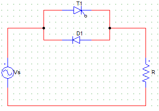
- a)half wave controller
- b)full wave controller
- c)none of the mentioned
- d)will depend upon the firing angle
Correct answer is option 'A'. Can you explain this answer?
The below shown controller circuit is a
a)
half wave controller
b)
full wave controller
c)
none of the mentioned
d)
will depend upon the firing angle
|
|
Sneha Bose answered |
As it consists one diode and one SCR only, the control is only in one cycle (the positive half in this case), hence it is a half wave controller.
A single phase voltage controller has input of 230 V and a load of 15 Ω resistive. For 6 cycles on and 4 cycles off, determine the rms output voltage.- a)189 V
- b)260 V
- c)156 V
- d)178 V
Correct answer is option 'D'. Can you explain this answer?
A single phase voltage controller has input of 230 V and a load of 15 Ω resistive. For 6 cycles on and 4 cycles off, determine the rms output voltage.
a)
189 V
b)
260 V
c)
156 V
d)
178 V
|
|
Arya Mukherjee answered |
Vrms = Vo x √k
k = (6/6+4) = 6/10 = 0.6
Vrms = √0.6 x 230 = 178.157 V.
k = (6/6+4) = 6/10 = 0.6
Vrms = √0.6 x 230 = 178.157 V.
If k is the duty cycles of the controller, then the rms value of the output voltage in case of a integral cycle control circuit will be?
Consider the input to be sinusoidal with peak value Vm and rms value Vs.- a)Vs x k
- b)Vs/k
- c)Vs x √k
- d)Vs
Correct answer is option 'C'. Can you explain this answer?
If k is the duty cycles of the controller, then the rms value of the output voltage in case of a integral cycle control circuit will be?
Consider the input to be sinusoidal with peak value Vm and rms value Vs.
Consider the input to be sinusoidal with peak value Vm and rms value Vs.
a)
Vs x k
b)
Vs/k
c)
Vs x √k
d)
Vs
|
|
Megha Datta answered |
Vrms = [ (k/2π) x ∫Vm2 sin2 ωt d(ωt) ] 1/2
Where the integral runs from 0 to 2π.
Vrms = (Vm/√2) k = Vs x √k.
Where the integral runs from 0 to 2π.
Vrms = (Vm/√2) k = Vs x √k.
High frequency gating uses a- a)train of pulses
- b)continuous gating block
- c)carrier signal
- d)none of the above
Correct answer is option 'A'. Can you explain this answer?
High frequency gating uses a
a)
train of pulses
b)
continuous gating block
c)
carrier signal
d)
none of the above
|
|
Nishtha Chauhan answered |
In high frequency gating a train of pulses are used to overcome the thermal problems due to continuous gating.
Applications of cycloconverters include- a)speed control of ac drives
- b)induction heating
- c)static VAr compensation
- d)all of the mentioned
Correct answer is option 'D'. Can you explain this answer?
Applications of cycloconverters include
a)
speed control of ac drives
b)
induction heating
c)
static VAr compensation
d)
all of the mentioned
|
|
Palak Verma answered |
Applications of Cycloconverters
Cycloconverters are power electronic devices that convert AC power at one frequency to AC power at another frequency. They are widely used in various industrial applications due to their versatility and ability to provide variable frequency and voltage output. Some of the common applications of cycloconverters include:
1. Speed Control of AC Drives:
Cycloconverters are extensively used in speed control systems for AC drives, especially in large industrial applications. By using cycloconverters, the speed of AC motors can be controlled efficiently and smoothly. This is achieved by varying the output frequency and voltage of the cycloconverter, which in turn controls the speed of the motor. This application is particularly useful in industries where precise control of motor speed is required, such as in conveyor systems, elevators, and machine tools.
2. Induction Heating:
Cycloconverters are also used in induction heating applications where high-frequency power is required. Induction heating is a process in which an electrically conductive material is heated by electromagnetic induction. Cycloconverters provide the necessary high-frequency power to generate the electromagnetic field required for induction heating. This application is commonly used in industries such as metal processing, forging, and heat treatment.
3. Static VAr Compensation:
Cycloconverters are utilized in static VAr compensation systems to regulate the reactive power in power transmission and distribution networks. Reactive power is required to maintain voltage stability in the grid and compensate for the reactive power demand of inductive loads. By using cycloconverters, the reactive power can be controlled and adjusted according to the system requirements. This helps in reducing voltage fluctuations, improving power factor, and enhancing the overall efficiency of the power system.
4. Other Applications:
Apart from the above-mentioned applications, cycloconverters find use in various other industrial and commercial applications. These include frequency conversion for testing electrical equipment, voltage conversion for specialized machinery, variable speed control for fans and pumps, and AC power generation for aerospace and marine applications.
In conclusion, cycloconverters have a wide range of applications in the field of power electronics. They are extensively used for speed control of AC drives, induction heating, static VAr compensation, and various other industrial applications. The ability to provide variable frequency and voltage output makes them highly versatile and suitable for a diverse range of applications.
The AC voltage controllers are used in __________ applications.- a)power generation
- b)electric heating
- c)conveyor belt motion
- d)power transmission
Correct answer is option 'B'. Can you explain this answer?
The AC voltage controllers are used in __________ applications.
a)
power generation
b)
electric heating
c)
conveyor belt motion
d)
power transmission
|
|
Srishti Choudhary answered |
In electric heating, variable ac supply is needed. The devices are fired appropriately to apply enough temperature.
In the integral cycle control method of ac voltage controller- a)the average power delivered to the load is controlled
- b)the instantaneous power delivered to the load is controlled
- c)the frequency of output voltage is controlled
- d)none of the mentioned
Correct answer is option 'A'. Can you explain this answer?
In the integral cycle control method of ac voltage controller
a)
the average power delivered to the load is controlled
b)
the instantaneous power delivered to the load is controlled
c)
the frequency of output voltage is controlled
d)
none of the mentioned
|
|
Kajal Mukherjee answered |
In integral cycle control, power is delivered for m cycles and not delivered for n cycles. Hence, the average value of the power delivered is controlled by manipulating m and n.
A single phase voltage controller has input of 230 V and a load of 15 Ω resistive. For 6 cycles on and 4 cycles off, determine the power delivered to the load.- a)2.1 W
- b)2.1 kW
- c)516 W
- d)5.16 kW
Correct answer is option 'B'. Can you explain this answer?
A single phase voltage controller has input of 230 V and a load of 15 Ω resistive. For 6 cycles on and 4 cycles off, determine the power delivered to the load.
a)
2.1 W
b)
2.1 kW
c)
516 W
d)
5.16 kW
|
|
Bibek Saha answered |
Calculation:
Given:
Input voltage = 230 V
Load resistance = 15 Ω
Cycles on = 6
Cycles off = 4
To find the power delivered to the load, we need to calculate the average power.
Average Power:
The average power delivered to a resistive load can be calculated using the formula:
Average Power = (1/T) * ∫(0 to T) [v(t) * i(t)] dt
Where:
T = Time period of the waveform
v(t) = Instantaneous voltage
i(t) = Instantaneous current
Time Period:
The time period of the waveform is the sum of the on and off cycles:
T = (cycles on + cycles off) * Time period of one cycle
Since one cycle consists of both on and off periods, the time period of one cycle can be found using the frequency:
f = 1 / Time period of one cycle
Frequency:
The frequency can be calculated using the formula:
f = 1 / Time period
Time Period of One Cycle:
The time period of one cycle can be calculated by dividing the time period by the sum of on and off cycles:
Time period of one cycle = Time period / (cycles on + cycles off)
Calculating Time period:
The time period can be calculated using the formula:
Time period = 1 / Frequency
Calculating Frequency:
The frequency can be calculated using the formula:
Frequency = 1 / Time period
Calculating Time period of One Cycle:
Substituting the values, we get:
Time period of one cycle = (1 / Frequency) / (cycles on + cycles off)
Calculating Average Power:
Substituting the values of voltage and current into the formula for average power, we get:
Average Power = (1 / Time period) * ∫(0 to Time period) [(v(t))^2 / R] dt
Since the load is resistive, the instantaneous current is given by Ohm's law:
i(t) = v(t) / R
Substituting this into the formula for average power, we get:
Average Power = (1 / Time period) * ∫(0 to Time period) [(v(t))^2 / R] dt
= (1 / Time period) * ∫(0 to Time period) [(v(t))^2 / R] dt
= (1 / Time period) * (1 / R) * ∫(0 to Time period) [(v(t))^2] dt
Since the voltage waveform is a sinusoidal waveform, the integral of the square of the voltage waveform over one time period is equal to the square of the RMS voltage:
∫(0 to Time period) [(v(t))^2] dt = (Vrms)^2 * Time period
Substituting this back into the formula for average power, we get:
Average Power = (1 / Time period) * (1 / R) * (Vrms)^2 * Time period
= (Vrms)^2 / R
Calculating RMS Voltage:
The RMS voltage can be calculated using the formula:
Vrms = Vm / √2
Where:
Vm = Maximum voltage
Calculating Maximum
In AC voltage controllers the- a)variable ac with fixed frequency is obtained
- b)variable ac with variable frequency is obtained
- c)variable dc with fixed frequency is obtained
- d)variable dc with variable frequency is obtained
Correct answer is option 'A'. Can you explain this answer?
In AC voltage controllers the
a)
variable ac with fixed frequency is obtained
b)
variable ac with variable frequency is obtained
c)
variable dc with fixed frequency is obtained
d)
variable dc with variable frequency is obtained
|
|
Partho Saha answered |
AC Voltage Controllers
AC voltage controllers are devices that allow for the control of AC voltage by varying the amplitude of the voltage waveform. They are commonly used in applications where precise control of AC voltage is required, such as in heating, lighting, and motor speed control.
Variable AC with Fixed Frequency
The main function of an AC voltage controller is to provide variable AC voltage with a fixed frequency. This is achieved by controlling the amplitude of the AC voltage waveform. The AC voltage controller uses a thyristor or a silicon-controlled rectifier (SCR) to control the voltage.
The thyristor or SCR is a solid-state device that can be turned on and off by a small control signal. When the thyristor is turned on, it conducts current in only one direction, allowing the AC voltage waveform to pass through. When the thyristor is turned off, it blocks the current flow and stops the AC voltage waveform.
The AC voltage controller uses a control circuit to turn the thyristor on and off at specific times during the AC voltage waveform. By varying the timing of the thyristor, the amplitude of the AC voltage waveform can be controlled, providing variable AC voltage with a fixed frequency.
Advantages of AC Voltage Controllers
AC voltage controllers have several advantages over other voltage control methods, including:
- High efficiency
- Precise control of AC voltage
- Low maintenance
- Compact size
- Low cost
Applications of AC Voltage Controllers
AC voltage controllers are commonly used in applications where precise control of AC voltage is required, such as:
- Heating systems
- Lighting systems
- Motor speed control
- Power supplies
- Welding equipment
Conclusion
In conclusion, AC voltage controllers provide variable AC voltage with a fixed frequency by controlling the amplitude of the AC voltage waveform using a thyristor or SCR. They have several advantages over other voltage control methods and are commonly used in applications where precise control of AC voltage is required.
A two stage sequence control is- a)two SCRs in anti parallel
- b)two voltage controllers in parallel
- c)two voltage controllers in series
- d)a voltage controller having two voltage level
Correct answer is option 'B'. Can you explain this answer?
A two stage sequence control is
a)
two SCRs in anti parallel
b)
two voltage controllers in parallel
c)
two voltage controllers in series
d)
a voltage controller having two voltage level
|
|
Mihir Khanna answered |
Sequence control of ac voltage controller means the use of two or more stages of voltage controllers in parallel for the regulation of output voltage.
In a three phase half-wave cycloconverter ___________- a)both inverting and converting action takes place
- b)only inversion action takes place
- c)only converting action takes place
- d)none of the mentioned
Correct answer is option 'A'. Can you explain this answer?
In a three phase half-wave cycloconverter ___________
a)
both inverting and converting action takes place
b)
only inversion action takes place
c)
only converting action takes place
d)
none of the mentioned
|
|
Pooja Patel answered |
During the conversion process, the current flows in both the directions, hence both inverting and converting action takes place.
The single phase bridge type cycloconverter uses __________ number of SCRs.- a)4
- b)8
- c)6
- d)none of the mentioned
Correct answer is option 'B'. Can you explain this answer?
The single phase bridge type cycloconverter uses __________ number of SCRs.
a)
4
b)
8
c)
6
d)
none of the mentioned
|
|
Pooja Patel answered |
4 negative and 4 positive SCRs are employed in bridge type cycloconverter.
In a N-stage sequence controller, each secondary is rated for __________- a)n x Vs
- b)Vs
- c)Vs/n
- d)Vs x (n-1)
Correct answer is option 'C'. Can you explain this answer?
In a N-stage sequence controller, each secondary is rated for __________
a)
n x Vs
b)
Vs
c)
Vs/n
d)
Vs x (n-1)
|
|
Surbhi Chopra answered |
In a N-stage sequence controller, each secondary is rated for Vs/n.
Explanation:
A sequence controller is a device used in power systems to control the sequential operation of various electrical equipment. It ensures that the equipment starts and stops in a specific order to prevent overloading or damage.
In a N-stage sequence controller, there are N secondary windings, each connected to a separate electrical load. The primary winding is connected to the power supply. The secondary windings are designed to have a specific voltage rating, Vs.
The voltage rating of each secondary winding in a N-stage sequence controller is given by Vs/n, where n represents the number of stages or secondary windings.
The reason for this is that the voltage across each secondary winding should be reduced to ensure proper operation of the connected electrical load. When multiple secondary windings are connected in a sequence controller, the total voltage is divided equally among them.
To achieve this division of voltage, the voltage rating of each secondary winding is set to Vs/n. This ensures that the voltage across each secondary winding is Vs/n, and the total voltage across all the secondary windings is Vs.
By providing the secondary windings with a voltage rating of Vs/n, the sequence controller ensures that each connected load receives the appropriate voltage level for its operation. This prevents overloading or damage to the electrical equipment.
Therefore, the correct answer is option c) Vs/n, where each secondary winding in a N-stage sequence controller is rated for Vs/n.
A single-phase two stage sequence controller is designed to work on 230 V supply, and upper and lower current ratings must be 20 A and 21 A respectively. Find the transformer rating.- a)230 VA
- b)4600 VA
- c)9430 VA
- d)9200 VA
Correct answer is option 'C'. Can you explain this answer?
A single-phase two stage sequence controller is designed to work on 230 V supply, and upper and lower current ratings must be 20 A and 21 A respectively. Find the transformer rating.
a)
230 VA
b)
4600 VA
c)
9430 VA
d)
9200 VA
|
|
Anoushka Choudhury answered |
Transformer rating is Vs(I1 + I2).
A cycloconverter is a _________- a)one stage power converter
- b)one stage voltage converter
- c)one stage frequency converter
- d)none of the mentioned
Correct answer is option 'C'. Can you explain this answer?
A cycloconverter is a _________
a)
one stage power converter
b)
one stage voltage converter
c)
one stage frequency converter
d)
none of the mentioned
|
|
Pooja Patel answered |
A cycloconverter converters input power at one frequency to output power at a different frequency with one-stage conversion.
Sequence control of ac voltage controllers is employed for the improvement of _________- a)output frequency
- b)input frequency
- c)commutation
- d)system power factor
Correct answer is option 'D'. Can you explain this answer?
Sequence control of ac voltage controllers is employed for the improvement of _________
a)
output frequency
b)
input frequency
c)
commutation
d)
system power factor
|
|
Anoushka Choudhury answered |
It is used to improve the power factor at both the input and output side.
A single-phase half wave voltage controller consists of- a)one SCR is parallel with one diode
- b)one SCR is anti parallel with one diode
- c)two SCRs in parallel
- d)two SCRs in anti parallel
Correct answer is option 'B'. Can you explain this answer?
A single-phase half wave voltage controller consists of
a)
one SCR is parallel with one diode
b)
one SCR is anti parallel with one diode
c)
two SCRs in parallel
d)
two SCRs in anti parallel
|
|
Anjali Choudhury answered |
As it is half wave, it consists of one SCR ( the control element) in anti parallel with one diode.
Earlier then the semiconductor technology, ___________ devices were used for voltage control applications.- a)cycloconverters
- b)vacuum tubes
- c)tap changing transformer
- d)induction machine
Correct answer is option 'C'. Can you explain this answer?
Earlier then the semiconductor technology, ___________ devices were used for voltage control applications.
a)
cycloconverters
b)
vacuum tubes
c)
tap changing transformer
d)
induction machine
|
|
Nandita Bajaj answered |
A tap changing transformer can give variable ac from fixed ac without a change in frequency.
Pulse gating is suitable for- a)R loads only
- b)R and RL loads
- c)RL loads only
- d)all types of loads
Correct answer is option 'A'. Can you explain this answer?
Pulse gating is suitable for
a)
R loads only
b)
R and RL loads
c)
RL loads only
d)
all types of loads
|
|
Malavika Nair answered |
In RL loads with pulse gating, the incoming SCR may be fired during the interval when it is reversed biased by the outgoing SCR, thus it won’t get turn on even after the outgoing SCR is not reveres basing the incoming SCR is the pulse width is over before forward biasing the SCR.
AC voltage controllers convert- a)fixed ac to fixed dc
- b)variable ac to variable dc
- c)fixed ac to variable ac
- d)variable ac to fixed ac
Correct answer is option 'C'. Can you explain this answer?
AC voltage controllers convert
a)
fixed ac to fixed dc
b)
variable ac to variable dc
c)
fixed ac to variable ac
d)
variable ac to fixed ac
|
|
Hiral Kulkarni answered |
AC voltage controllers are electronic devices used to control the voltage of an alternating current (AC) power supply. They are commonly used in applications where precise control of the output voltage is required, such as in industrial machinery, motor speed control, and power supplies for electronic devices.
The correct answer is option 'C', which states that AC voltage controllers convert fixed AC to variable AC. This means that they take a fixed AC input voltage and provide a variable AC output voltage, allowing for control and adjustment of the voltage level.
Here is a detailed explanation of why option 'C' is the correct answer:
1. AC to AC Conversion:
AC voltage controllers are designed to perform AC to AC conversion. They take an AC input voltage, which is typically fixed at a specific frequency and amplitude, and convert it into a variable AC output voltage.
2. Fixed AC input:
The input voltage to an AC voltage controller is usually fixed at a specific frequency and amplitude. This means that the input voltage remains constant throughout the operation of the controller. It could be sourced from the mains power supply or from a generator.
3. Variable AC output:
The primary function of an AC voltage controller is to provide a variable AC output voltage. This means that the controller can adjust the output voltage level based on the desired requirements. The output voltage can be increased or decreased as needed, allowing for precise control of the voltage.
4. Control methods:
AC voltage controllers use various control methods to adjust the output voltage. One common method is phase control, where the firing angle of the thyristors or other solid-state switching devices is adjusted to control the portion of the input waveform that is transferred to the output. This allows for smooth and continuous control of the output voltage.
5. Applications:
AC voltage controllers find applications in various industries and systems. They are commonly used in motor speed control, where the output voltage is adjusted to control the speed of AC motors. They are also used in power supplies for electronic devices, where the output voltage needs to be precisely regulated.
In conclusion, AC voltage controllers convert fixed AC input voltage to variable AC output voltage. They are used in applications where precise control of the voltage level is required.
The SCR T1 is fired at an angle of α, and the supply Vs = Vm sinωt. Find the average value of the output voltage.
- a)(Vm/2π) (cosα + )
- b)(Vm/2π) (cosα)
- c)(Vm/2π) (cosα – 1)
- d)Vm
Correct answer is option 'C'. Can you explain this answer?
The SCR T1 is fired at an angle of α, and the supply Vs = Vm sinωt. Find the average value of the output voltage.
a)
(Vm/2π) (cosα + )
b)
(Vm/2π) (cosα)
c)
(Vm/2π) (cosα – 1)
d)
Vm
|
|
Srishti Choudhary answered |
Vo = (1/2π) ∫Vm sinωt d(ωt). Where the integration would be run from α to 2π as the conduction takes place from α to 2π.
Vo = (Vm/2π) (cosα – 1).
Vo = (Vm/2π) (cosα – 1).
Find the power delivered to the load in the integral cycle control method of ac voltage control, having a sine input of Vs, R load and duty cycle = k.
- a)Vs2/R
- b)k.Vs2/R
- c)√k .Vs2/R
- d)0
Correct answer is option 'B'. Can you explain this answer?
Find the power delivered to the load in the integral cycle control method of ac voltage control, having a sine input of Vs, R load and duty cycle = k.
a)
Vs2/R
b)
k.Vs2/R
c)
√k .Vs2/R
d)
0
|
|
Sahil Datta answered |
Output voltage = Vs x √k
P = (Vs x √k)2/R.
P = (Vs x √k)2/R.
In the integral cycle control method with duty cycle = k and maximum load current = Im. Find the value of average SCR current.
- a)Im/k.π
- b)Im
- c)k.Im
- d)k.Im/π
Correct answer is option 'D'. Can you explain this answer?
In the integral cycle control method with duty cycle = k and maximum load current = Im. Find the value of average SCR current.
a)
Im/k.π
b)
Im
c)
k.Im
d)
k.Im/π
|
|
Gargi Mishra answered |
As each SCR conducts for π radians during each cycle of n on cycles, the average value of SCR current is
I = (k/2π) ∫Im sin ωt d(ωt). Where the integration is from 0 to π.
I = (k/2π) ∫Im sin ωt d(ωt). Where the integration is from 0 to π.
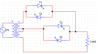
In the positive half cycle, _________ SCRs are forward biased.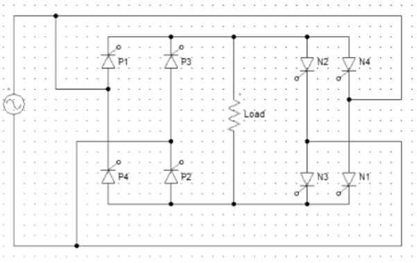
- a)P1, P2, N1, N2
- b)P1, P2, P3, P4
- c)N1, N2, N3, N4
- d)P3, P4, N1, N2
Correct answer is option 'A'. Can you explain this answer?
In the positive half cycle, _________ SCRs are forward biased.
a)
P1, P2, N1, N2
b)
P1, P2, P3, P4
c)
N1, N2, N3, N4
d)
P3, P4, N1, N2
|
|
Pooja Patel answered |
Pairs P1, P2 and N1, N2 are forward biased from ωt = 0 to π.
In the positive half cycle from ωt = 0 to π
- a)P1 and P2 are forward biased
- b)N1 and P2 are forward biased
- c)P1 and N2 are forward biased
- d)None of the mentioned
Correct answer is option 'C'. Can you explain this answer?
In the positive half cycle from ωt = 0 to π
a)
P1 and P2 are forward biased
b)
N1 and P2 are forward biased
c)
P1 and N2 are forward biased
d)
None of the mentioned
|
|
Pooja Patel answered |
In the positive half cycle, upper terminal is positive of the upper secondary and the lower terminal is negative for the lower secondary. Hence, P1 and N2 are forward biased.
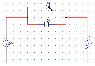
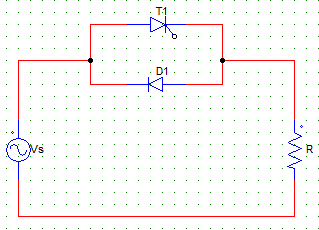
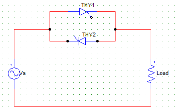
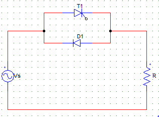
The below given controller circuit is a
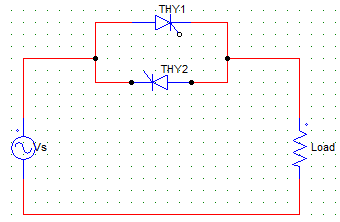
- a)half wave controller
- b)full wave controller
- c)none of the mentioned
- d)will depend upon the firing angle
Correct answer is option 'B'. Can you explain this answer?
The below given controller circuit is a
a)
half wave controller
b)
full wave controller
c)
none of the mentioned
d)
will depend upon the firing angle
|
|
Anshika Nambiar answered |
As it consists of two SCRs, it is a full wave controller.
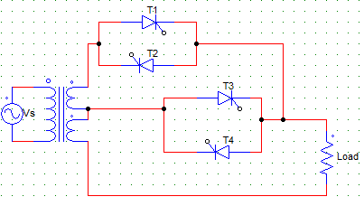
In the below given cycloconverter circuit, _________ and _________ conduct in one cycle together.
- a)P1, P2 and N1, N2
- b)P1, N2 and N1, P2
- c)N1, P1 and N1, P2
- d)None of the mentioned
Correct answer is option 'B'. Can you explain this answer?
In the below given cycloconverter circuit, _________ and _________ conduct in one cycle together.
a)
P1, P2 and N1, N2
b)
P1, N2 and N1, P2
c)
N1, P1 and N1, P2
d)
None of the mentioned
|
|
Pooja Patel answered |
In the positive half cycle, upper terminal is positive of the upper secondary and the lower terminal is negative for the lower secondary. Hence, P1 and N2 are forward biased. And likewise, N1 and P2 will conduct in the next half cycle.
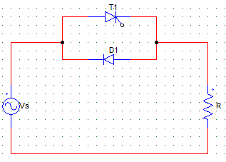
In the below shown circuit, the diode conducts for
- a)90°
- b)> 90°
- c)< 90°
- d)0°
Correct answer is option 'A'. Can you explain this answer?
In the below shown circuit, the diode conducts for
a)
90°
b)
> 90°
c)
< 90°
d)
0°
|
|
Poulomi Chopra answered |
The diode conducts from π to 2π in the negative half cycle. If it were a non resistive load, the diode would conduct for less than 90°, as the inductor would force conduct the SCR for some time.
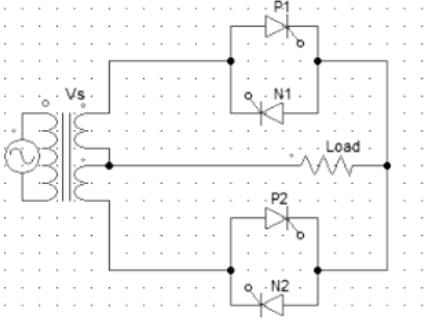
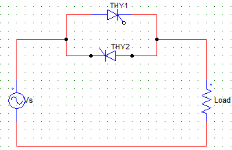
In the below given voltage controller circuit
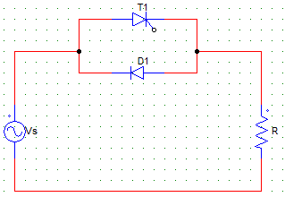
- a)the positive half cycle at the load is same as the supply Vs
- b)the negative half cycle at the load is same as the supply Vs
- c)the positive and negative half cycles at the load are identical to the supply
- d)none of the mentioned
Correct answer is option 'B'. Can you explain this answer?
In the below given voltage controller circuit
a)
the positive half cycle at the load is same as the supply Vs
b)
the negative half cycle at the load is same as the supply Vs
c)
the positive and negative half cycles at the load are identical to the supply
d)
none of the mentioned
|
|
Bhavana Reddy answered |
As T1 is triggered at an angle α, the conduction in the positive have cycle will start at α. In the negative half cycle, the diode is forward biased and load is connected as it is to the supply.
The below given circuit has Vs = 230V and R = 20 Ω. Find the value of the average output voltage at the R load for a firing angle of 45°.
- a)224 V
- b)-15.17 V
- c)15.17 V
- d)–224 V
Correct answer is option 'B'. Can you explain this answer?
The below given circuit has Vs = 230V and R = 20 Ω. Find the value of the average output voltage at the R load for a firing angle of 45°.
a)
224 V
b)
-15.17 V
c)
15.17 V
d)
–224 V
|
|
Poulomi Chopra answered |
Vo = [(√2 x 230) x (cos45 – 1)]/2π = -15.17 V.
Negative value is due to the fact that the average value in the positive half cycle is less than that in the negative half cycle.
Negative value is due to the fact that the average value in the positive half cycle is less than that in the negative half cycle.
The below given output voltage waveform can be obtained by a
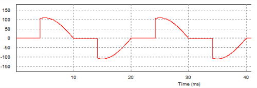
- a)half wave ac voltage controller
- b)full wave ac voltage controller
- c)full wave inverter circuit
- d)none of the mentioned
Correct answer is option 'B'. Can you explain this answer?
The below given output voltage waveform can be obtained by a
a)
half wave ac voltage controller
b)
full wave ac voltage controller
c)
full wave inverter circuit
d)
none of the mentioned
|
|
Bhavana Reddy answered |
As the control is in both the directions or cycles, it is a full wave ac voltage controller circuit.
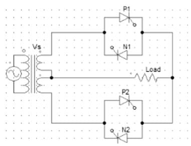
The below given circuit is that of a
- a)four stage sequence controller
- b)two stage sequence controller
- c)full wave ac voltage controller
- d)none of the mentioned
Correct answer is option 'B'. Can you explain this answer?
The below given circuit is that of a
a)
four stage sequence controller
b)
two stage sequence controller
c)
full wave ac voltage controller
d)
none of the mentioned
|
|
Anjali Choudhury answered |
Sequence control of ac voltage controller means the use of two or more stages of voltage controllers in parallel for the regulation of output voltage.
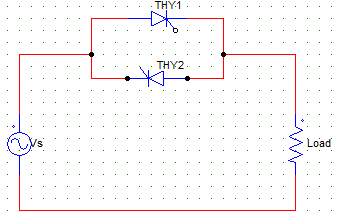
In the below shown AC converter circuit with firing angle = α for both the devices, T2 will conduct from
- a)α to π
- b)π + α to 2π
- c)π to 2π
- d)α to 2π
Correct answer is option 'B'. Can you explain this answer?
In the below shown AC converter circuit with firing angle = α for both the devices, T2 will conduct from
a)
α to π
b)
π + α to 2π
c)
π to 2π
d)
α to 2π
|
|
Poulomi Ahuja answered |
T2 is triggered at π + α, it conducts from π + α to 2π after which it is line commutated.
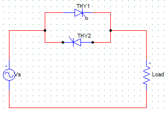
In the below given voltage controller circuit
- a)only the negative cycle can be controlled
- b)only the positive cycle can be controlled
- c)both the cycles can be controlled
- d)none of the mentioned
Correct answer is option 'C'. Can you explain this answer?
In the below given voltage controller circuit
a)
only the negative cycle can be controlled
b)
only the positive cycle can be controlled
c)
both the cycles can be controlled
d)
none of the mentioned
|
|
Avantika Kaur answered |
As it consists of two SCRs, it is a full wave controller and both the half cycles can be controlled by varying their respective firing angles.
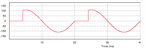
The below given output voltage waveform can be obtained by a
- a)half wave ac voltage controller
- b)full wave ac voltage controller
- c)half wave controller with firing angle = 0° for T1
- d)full wave controller with firing angle = 0° for both T1 and T2
Correct answer is option 'A'. Can you explain this answer?
The below given output voltage waveform can be obtained by a
a)
half wave ac voltage controller
b)
full wave ac voltage controller
c)
half wave controller with firing angle = 0° for T1
d)
full wave controller with firing angle = 0° for both T1 and T2
|
|
Gargi Mishra answered |
As the positive half is chopped off due to some value of firing angle, the firing angle is not equal to zero. As the negative half is a half sine wave, either it is a full wave controller with firing angle for T2 set to zero or it is a half wave controller with a Thyristor (T1) and a diode.
The below given circuit has Vs = 230V and R = 20 Ω. Find the value of the average output load current at the R load for a firing angle of 45°.
- a)– 0.7585
- b)0.7585
- c)-0.6396
- d)-0.5
Correct answer is option 'A'. Can you explain this answer?
The below given circuit has Vs = 230V and R = 20 Ω. Find the value of the average output load current at the R load for a firing angle of 45°.
a)
– 0.7585
b)
0.7585
c)
-0.6396
d)
-0.5
|
|
Poulomi Ahuja answered |
Vo = [(√2 x 230) x (cos45 – 1)]/2π = -15.17 V.
Io = (Vo)/R = -0.7585
Negative value is due to the fact that the average value in the positive half cycle is less than that in the negative half cycle.
Io = (Vo)/R = -0.7585
Negative value is due to the fact that the average value in the positive half cycle is less than that in the negative half cycle.
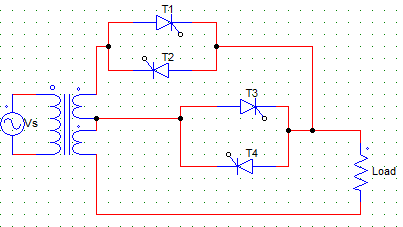
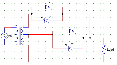
If T1, T2 are kept off and T3, T4 are having a firing angle of 180° each, then the output voltage is ____ if the turns ratio is 1:1
- a)Vs
- b)√2Vs
- c)0
- d)2Vs
Correct answer is option 'C'. Can you explain this answer?
If T1, T2 are kept off and T3, T4 are having a firing angle of 180° each, then the output voltage is ____ if the turns ratio is 1:1
a)
Vs
b)
√2Vs
c)
0
d)
2Vs
|
|
Akanksha Chopra answered |
If T3 and T4 are fired at an angle of 180°, they are equivalent to an off switch, as they are fired and naturally commutated at the same time, hence they are never on.
Hence, as all the four SCRs are always off, the output voltage is zero.
Hence, as all the four SCRs are always off, the output voltage is zero.
For obtaining the output voltage control from V to 2V, the firing angle must be
- a)always 0 for T3, T4
- b)always 180 for T3, T4
- c)0 to 180 from T3, T4
- d)none of the mentioned
Correct answer is option 'A'. Can you explain this answer?
For obtaining the output voltage control from V to 2V, the firing angle must be
a)
always 0 for T3, T4
b)
always 180 for T3, T4
c)
0 to 180 from T3, T4
d)
none of the mentioned
|
|
Sanskriti Kaur answered |
For obtaining the voltage control from V to 2V, the lower controller i.e. T3, T4 pair must always be on hence the firing angle from them must always be 0° ideally.
For obtaining the output voltage control from V to 2V, the firing angle must be
- a)always 0 for T1, T2
- b)always 180 for T1, T2
- c)0 to 180 from T1, T2
- d)none of the mentioned
Correct answer is option 'C'. Can you explain this answer?
For obtaining the output voltage control from V to 2V, the firing angle must be
a)
always 0 for T1, T2
b)
always 180 for T1, T2
c)
0 to 180 from T1, T2
d)
none of the mentioned
|
|
Preethi Banerjee answered |
For obtaining the voltage control from V to 2V, the upper controller must be controlled by varying its firing angle from 0 to 180° whereas the T3, T4 pair must always be on hence the firing angle from them must always be 0° ideally.
Chapter doubts & questions for AC Voltage Controllers & Cyclo Converters - Power Electronics 2025 is part of Electrical Engineering (EE) exam preparation. The chapters have been prepared according to the Electrical Engineering (EE) exam syllabus. The Chapter doubts & questions, notes, tests & MCQs are made for Electrical Engineering (EE) 2025 Exam. Find important definitions, questions, notes, meanings, examples, exercises, MCQs and online tests here.
Chapter doubts & questions of AC Voltage Controllers & Cyclo Converters - Power Electronics in English & Hindi are available as part of Electrical Engineering (EE) exam.
Download more important topics, notes, lectures and mock test series for Electrical Engineering (EE) Exam by signing up for free.
Power Electronics
5 videos|67 docs|46 tests
|
|
© EduRev
|
Education Revolution
|


|


Signup to see your scores
go up within 7 days!
Access 1000+ FREE Docs, Videos and Tests
Takes less than 10 seconds to signup