


All Exams >
Electrical Engineering (EE) >
Power Electronics >
All Questions
All questions of Thyristors for Electrical Engineering (EE) Exam
After firing an SCR, the gate pulse is removed. The current in the SCR will- a)rise up.
- b)remain the same.
- c)rise a little and then fall to zero.
- d)immediately fall to zero.
Correct answer is option 'B'. Can you explain this answer?
After firing an SCR, the gate pulse is removed. The current in the SCR will
a)
rise up.
b)
remain the same.
c)
rise a little and then fall to zero.
d)
immediately fall to zero.
|
|
Ravi Singh answered |
Once the thyristor (SCR) is turned-on, and the anode current is above latching current level, there is no need of gate current, hence, gate signal can be withdrawn i.e. gate looses control over the anode current.

The natural reversal of ac supply voltage commutates the SCR in case of- a)forced commutation
- b)only line commutation
- c)only natural commutation
- d)both line & natural commutation
Correct answer is option 'D'. Can you explain this answer?
The natural reversal of ac supply voltage commutates the SCR in case of
a)
forced commutation
b)
only line commutation
c)
only natural commutation
d)
both line & natural commutation
|
|
Sakshi Tiwari answered |
Both line and natural commuataion are used in converters.
In case of class B commutation or resonant-pulse commutation with L = 5 μH and C = 20 μC with initial voltage across the capacitor (Vs) = 230 V. Find the peak value of resonant current.- a)560 A
- b)460 A
- c)360 A
- d)260 A
Correct answer is option 'B'. Can you explain this answer?
In case of class B commutation or resonant-pulse commutation with L = 5 μH and C = 20 μC with initial voltage across the capacitor (Vs) = 230 V. Find the peak value of resonant current.
a)
560 A
b)
460 A
c)
360 A
d)
260 A
|
|
Aman Jain answered |
Ip = Vs x √C/L.
The major function of the pulse transformer is to- a)increase the voltage amplitude
- b)reduce harmonics
- c)isolate low & high power circuit
- d)create periodic pulses
Correct answer is option 'C'. Can you explain this answer?
The major function of the pulse transformer is to
a)
increase the voltage amplitude
b)
reduce harmonics
c)
isolate low & high power circuit
d)
create periodic pulses
|
|
Ritika Sarkar answered |
Isolation of the two circuit is done by the transformer, as the transformer is a magnetically coupled device and any mishap at the load side will not damage the other side of the circuitry.
A triac is a semi-conductor device which acts as a- a)2 Terminal unidirectional switch
- b)2 Terminal bidirectional switch
- c)3 Terminal bidirectional switch
- d)5 terminal multi-directional switch
Correct answer is option 'C'. Can you explain this answer?
A triac is a semi-conductor device which acts as a
a)
2 Terminal unidirectional switch
b)
2 Terminal bidirectional switch
c)
3 Terminal bidirectional switch
d)
5 terminal multi-directional switch
|
|
Mihir Khanna answered |
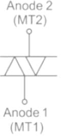
Triac as a 3 Terminal Bidirectional Switch
A triac is a semiconductor device that acts as a bidirectional switch and is commonly used in AC power control applications. It is a three-terminal device that can conduct current in both directions when triggered appropriately. The correct answer to the given question is option 'C', which states that a triac is a three-terminal bidirectional switch.
Three-Terminal Device
A triac consists of three terminals: Main Terminal 1 (MT1), Main Terminal 2 (MT2), and Gate (G). These terminals are used to control the flow of current through the device.
Bidirectional Switch
A bidirectional switch is a device that can control the flow of current in both directions. Unlike a unidirectional switch, which can only conduct current in one direction, a bidirectional switch is suitable for AC power control applications where the current periodically changes direction.
Working Principle
A triac is a two-way thyristor, meaning it can conduct current in both directions. It consists of two SCR (Silicon Controlled Rectifier) structures connected in parallel but in opposite directions. The operation of a triac can be understood by considering the four quadrants of its operation.
1. Quadrant I: In this quadrant, the voltage across MT1 and MT2 is positive, and the gate current is positive. The triac is forward-biased, and it conducts current. This quadrant represents the positive half-cycle of an AC waveform.
2. Quadrant II: In this quadrant, the voltage across MT1 and MT2 is negative, and the gate current is positive. The triac is reverse-biased, and it does not conduct current. This quadrant represents the negative half-cycle of an AC waveform.
3. Quadrant III: In this quadrant, the voltage across MT1 and MT2 is negative, and the gate current is negative. The triac is forward-biased, and it conducts current. This quadrant represents the negative half-cycle of an AC waveform.
4. Quadrant IV: In this quadrant, the voltage across MT1 and MT2 is positive, and the gate current is negative. The triac is reverse-biased, and it does not conduct current. This quadrant represents the positive half-cycle of an AC waveform.
Applications
Due to its bidirectional switching capability, a triac is widely used in various AC power control applications such as:
1. Dimmer switches: Triacs are commonly used in lighting control circuits to adjust the brightness of incandescent lamps.
2. Motor speed control: Triacs can be used to control the speed of AC motors.
3. Heating control: Triacs are used in electric heaters and ovens for temperature control.
4. Power control: Triacs are used for power regulation in AC circuits.
In conclusion, a triac is a three-terminal bidirectional switch that can conduct current in both directions when triggered appropriately. It is a versatile device widely used in AC power control applications.
In case of a R firing with R2 as the variable resistance, Vgp (peak of gate voltage) and Vgt(gate triggering voltage) the value of R2 is so adjusted such that- a)Vgp = Vgt
- b) Vgp > Vgt
- c)Vgp < Vgt
- d)Vgp = Vgt = 0
Correct answer is option 'A'. Can you explain this answer?
In case of a R firing with R2 as the variable resistance, Vgp (peak of gate voltage) and Vgt(gate triggering voltage) the value of R2 is so adjusted such that
a)
Vgp = Vgt
b)
Vgp > Vgt
c)
Vgp < Vgt
d)
Vgp = Vgt = 0
|
|
Abhay Khanna answered |
For turning on the device, the peak of gate voltage must be equal to the gate triggering voltage.
Assertion (A): Single phase half-wave converter introduces a dc component into the supply line.
Reason (R) : The supply current taken from the source is unidirectional and is in the form of dc pulses- a)Both A and R are true and R is the correct explanation of A.
- b)Both A and R are true but R is not the correct explanation of A,
- c)A is true but R is false.
- d)A is false but R is true.
Correct answer is option 'A'. Can you explain this answer?
Assertion (A): Single phase half-wave converter introduces a dc component into the supply line.
Reason (R) : The supply current taken from the source is unidirectional and is in the form of dc pulses
Reason (R) : The supply current taken from the source is unidirectional and is in the form of dc pulses
a)
Both A and R are true and R is the correct explanation of A.
b)
Both A and R are true but R is not the correct explanation of A,
c)
A is true but R is false.
d)
A is false but R is true.
|
|
Gaurav Chauhan answered |
Assertion (A): Single phase half-wave converter introduces a dc component into the supply line.
Reason (R): The supply current taken from the source is unidirectional and is in the form of dc pulses.
The correct answer is option 'A', which means that both the assertion and reason are true, and the reason is the correct explanation of the assertion.
Explanation:
In order to understand the given assertion and reason, let's break it down into two parts and discuss each part separately.
Part 1: Single phase half-wave converter introduces a dc component into the supply line
Single phase half-wave converter is a rectifier circuit that converts alternating current (AC) into pulsating direct current (DC). It consists of a diode connected in series with a load and an AC source. The diode allows current to flow only in one direction, which means it allows only the positive half-cycle of the input AC waveform to pass through. During the negative half-cycle, the diode blocks the current.
As a result, the output current of the half-wave converter is a pulsating DC waveform, where the current flows only during the positive half-cycle and becomes zero during the negative half-cycle. This pulsating DC waveform has a significant ripple component, which means it is not pure DC. However, this pulsating DC waveform does have a constant, non-zero component, known as the DC component.
Therefore, it can be concluded that a single phase half-wave converter introduces a DC component into the supply line.
Part 2: The supply current taken from the source is unidirectional and is in the form of DC pulses
The supply current taken from the source in a single phase half-wave converter is unidirectional, meaning it flows in only one direction. During the positive half-cycle of the input AC waveform, the diode allows the current to flow through the load, creating a positive pulse of current. However, during the negative half-cycle, the diode blocks the current, resulting in zero current flow.
This means that the supply current taken from the source is in the form of DC pulses, where the current flows only during the positive half-cycle and is zero during the negative half-cycle.
Therefore, it can be concluded that the supply current taken from the source in a single phase half-wave converter is unidirectional and in the form of DC pulses.
Conclusion:
The assertion that a single phase half-wave converter introduces a DC component into the supply line is true, and the reason that the supply current taken from the source is unidirectional and in the form of DC pulses is the correct explanation of this assertion. Hence, the correct answer is option 'A'.
For a thysistor maximum junction temperature is 200°C. The thermal resistance for the thyristor sink combination are θJC = 0.15 and θCS = 0.05∘c/w. Initially the heat sink temperature of 80° C and it is brought down to 70° C by force cooling, the percentage increase in the device rating is – (in%)
Correct answer is between '4,4.1'. Can you explain this answer?
For a thysistor maximum junction temperature is 200°C. The thermal resistance for the thyristor sink combination are θJC = 0.15 and θCS = 0.05∘c/w. Initially the heat sink temperature of 80° C and it is brought down to 70° C by force cooling, the percentage increase in the device rating is – (in%)
|
|
Nitya Chopra answered |
The maximum junction temperature for a thyristor is typically around 125°C to 150°C. However, it is important to note that the actual maximum junction temperature can vary depending on the specific manufacturer and model of the thyristor. It is always recommended to refer to the datasheet provided by the manufacturer for the exact maximum junction temperature specification.
In case of an RC full wave firing circuit with R load, the voltage across the load is zero for____________- a)ωt = 0 to α and ωt = π to 2π+α
- b)ωt = 0 to α
- c)ωt = π to 2π+α
- d)ωt = α to 2π
Correct answer is option 'B'. Can you explain this answer?
In case of an RC full wave firing circuit with R load, the voltage across the load is zero for____________
a)
ωt = 0 to α and ωt = π to 2π+α
b)
ωt = 0 to α
c)
ωt = π to 2π+α
d)
ωt = α to 2π
|
|
Manoj Chaudhary answered |
The SCR is not triggered(turned-on) until α, hence no current flows until α.
In case of a R firing circuit with Vgp > Vgt- a)α = 90°
- b)α > 90°
- c)α < 90°
- d)α = 0°
Correct answer is option 'C'. Can you explain this answer?
In case of a R firing circuit with Vgp > Vgt
a)
α = 90°
b)
α > 90°
c)
α < 90°
d)
α = 0°
|
|
Charvi Reddy answered |
For the values of Vgp great than the gate triggering voltage the firing angle is less than 90°. And for Vgp = Vgt the firing angle is equal to 90°. Α cannot go beyond 90° in case of a R firing circuit.
The SCR is turned OFF when the anode current is ______ holding current- a)below
- b)above
- c)equal to
- d)twice the
Correct answer is option 'A'. Can you explain this answer?
The SCR is turned OFF when the anode current is ______ holding current
a)
below
b)
above
c)
equal to
d)
twice the
|
|
Pooja Patel answered |
The turn-off time of SCR:
- Once the thyristor is switched ON (the anode current is above latching current), the gate loses control over it. That means the gate circuit cannot turn off the device.
- For turning off the SCR anode current must fall below the holding current. After the anode current falls to zero, we cannot apply a forward voltage across the device due to the presence of the carrier. So, we must sweep out or recombine these charges to proper turn off of SCR.
- So, the turn-off time of SCR can be defined as the interval between anode current falls to zero and the device regains its forward blocking mode.
Circuit turn-off time:
- It is defined as the time during which a reverse voltage is applied across the thyristor during its commutation process.
- An SCR is turned off when its turn-off time is less than the circuit turn-off time.
Note:
- If the circuit turn-off time is less than the device turn-off time then forward bias voltage gets applied across even before the thyristor could regain its forward blocking capabilities and gets turn on again or the device turn-off is unsuccessful.
Assertion (A): The commutation overlap is more predominant is semiconverters than in full converters.
Reason (R): The commutation period in seconds, when outgoing and incoming SCRs are conducting, is known as the overlap period.- a)Both A and R are true and R is the correct explanation of A.
- b)Both A and R are true but R is not the correct explanation of A.
- c)A is true but R is false.
- d)A is false but R is true.
Correct answer is option 'D'. Can you explain this answer?
Assertion (A): The commutation overlap is more predominant is semiconverters than in full converters.
Reason (R): The commutation period in seconds, when outgoing and incoming SCRs are conducting, is known as the overlap period.
Reason (R): The commutation period in seconds, when outgoing and incoming SCRs are conducting, is known as the overlap period.
a)
Both A and R are true and R is the correct explanation of A.
b)
Both A and R are true but R is not the correct explanation of A.
c)
A is true but R is false.
d)
A is false but R is true.
|
|
Poulomi Chopra answered |
The commutation overlap is more predominant in full converter than in semi converter. Hence, assertion is a false statement.
Find the amplitude of the gate current pulse, when the gate-cathode curve is given by the relation Vg = [(1+10) x Ig] The peak gate drive power is 5 Watts.- a)359mA
- b)659mA
- c)1.359 A
- d)1.659 A
Correct answer is option 'B'. Can you explain this answer?
Find the amplitude of the gate current pulse, when the gate-cathode curve is given by the relation Vg = [(1+10) x Ig] The peak gate drive power is 5 Watts.
a)
359mA
b)
659mA
c)
1.359 A
d)
1.659 A
|
|
Sanskriti Bajaj answered |
(1+10 Ig).Ig = 5 Watts
Ig = 0.59 A.
Ig = 0.59 A.
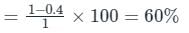
An SCR has ambient temperature of 25°C and Junction temperature of 50°C and Average power dissipated of 25 watt. If the junction temperature is reduced to 35°C, the percentage reduction in thermal resistance _______
Correct answer is '60'. Can you explain this answer?
An SCR has ambient temperature of 25°C and Junction temperature of 50°C and Average power dissipated of 25 watt. If the junction temperature is reduced to 35°C, the percentage reduction in thermal resistance _______
|
|
Pooja Patel answered |
Concept
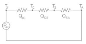 Here,
Here,Pav = Average rate of heat generated at a thyristor Junction
QJC = thermal resistance between the junction temperature TJ and case temperature TC
QCS = thermal resistance between the case temperature TC and sink temperature
QSA = thermal resistance between the sink temperature TS and ambient temperature TA
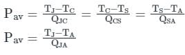
Where QJA = QJC + QCS + QSA
Calculations:
TA = 25°C
IJ = 50°C
Pav = 25 watt
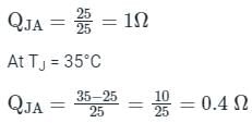
∴ % change in thermal resistance
Which of the following is used for turning ON DIAC?- a)High voltage on anode
- b)Break over voltage
- c)Gate voltage
- d)Gate current
Correct answer is option 'B'. Can you explain this answer?
Which of the following is used for turning ON DIAC?
a)
High voltage on anode
b)
Break over voltage
c)
Gate voltage
d)
Gate current
|
|
Pooja Patel answered |
DIAC:
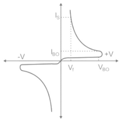
- The DIAC is a diode that conducts electrical current only after its break over-voltage, VBO, has been reached momentarily.
- A DIAC is equivalent to a pair of four-layer SCRs.
- A DIAC has two PN terminals.
The firing-angle delay is- a)inversely proportional to the synchronizing transformer voltage
- b)inversely proportional to the control signal voltage
- c)directly proportional to the synchronizing transformer voltage
- d)directly proportional to the control signal voltage
Correct answer is option 'D'. Can you explain this answer?
The firing-angle delay is
a)
inversely proportional to the synchronizing transformer voltage
b)
inversely proportional to the control signal voltage
c)
directly proportional to the synchronizing transformer voltage
d)
directly proportional to the control signal voltage
|
|
Neha Nambiar answered |
If Ec is lowered the firing angle decreases & vice-verse.
TRIAC is used in- a)Colour TV sets
- b)Black and White TV sets
- c)Tape-recorders
- d)Audio systems
Correct answer is option 'A'. Can you explain this answer?
TRIAC is used in
a)
Colour TV sets
b)
Black and White TV sets
c)
Tape-recorders
d)
Audio systems
|
|
Jatin Mukherjee answered |
Explanation:
TRIAC, which stands for Triode for Alternating Current, is a three-terminal electronic component that is widely used in various electrical and electronic applications. It is a type of thyristor that can conduct in both directions, allowing it to control AC power.
Usage in Colour TV sets:
TRIACs are commonly used in colour TV sets for controlling the power supplied to the CRT (Cathode Ray Tube) display. The TRIAC is used in the horizontal deflection circuit, where it controls the flow of current through the deflection coil. By adjusting the firing angle of the TRIAC, the horizontal deflection can be controlled, resulting in the movement of the electron beam across the screen, which produces the image.
Usage in Black and White TV sets:
Although TRIACs are more commonly used in colour TV sets, they can also be used in black and white TV sets. In black and white TV sets, TRIACs can be used in the power supply circuit to control the AC voltage supplied to different sections of the TV, such as the audio amplifier, video amplifier, and tuner.
Usage in Tape-recorders:
TRIACs can also be found in tape recorders and other audio equipment. In tape recorders, TRIACs are used for controlling the motor speed. The TRIAC acts as a switch, turning the motor on and off as needed to maintain the desired speed of the tape.
Usage in Audio systems:
TRIACs are used in audio systems for various purposes. They can be used in volume control circuits, where they control the power supplied to the audio amplifier. TRIACs can also be used in dimmer circuits for controlling the brightness of indicator lights or displays on audio equipment.
In conclusion, while TRIACs can be used in a variety of electrical and electronic applications, they are commonly used in colour TV sets for controlling the horizontal deflection and in tape recorders and audio systems for motor speed control and power regulation.
Which one of the following is/are not true with reference to a thyristor?1. Latching current (IL) is associated with the turn-off process and holding current (IH) with the turn-on process.
2. Holding current is associated with the turn-off process and latching current with the turn-on process
3. A thyristor can be termed as an AC switch- a)Both 1 & 2 are correct.
- b)Only 2 & 3 are correct
- c)Only 2 is correct
- d)Only 1 is correct
Correct answer is option 'C'. Can you explain this answer?
Which one of the following is/are not true with reference to a thyristor?
1. Latching current (IL) is associated with the turn-off process and holding current (IH) with the turn-on process.
2. Holding current is associated with the turn-off process and latching current with the turn-on process
3. A thyristor can be termed as an AC switch
2. Holding current is associated with the turn-off process and latching current with the turn-on process
3. A thyristor can be termed as an AC switch
a)
Both 1 & 2 are correct.
b)
Only 2 & 3 are correct
c)
Only 2 is correct
d)
Only 1 is correct
|
|
Ritika Sarkar answered |
And 2
b)Only 1
c)Only 2
d)None of the above
b)Only 1
c)Only 2
d)None of the above
The drawback of fi-firing circuit for SCR is- a)firing angle limitation to
- b)reduced response time π/2
- c)high power loss
- d)requirement of high on-time of SCRs
Correct answer is option 'A'. Can you explain this answer?
The drawback of fi-firing circuit for SCR is
a)
firing angle limitation to
b)
reduced response time π/2
c)
high power loss
d)
requirement of high on-time of SCRs
|
|
Nilesh Joshi answered |
The R-firing circuit suffers from several disadvantages. One of them is that the trigger angle can be varied only upto an approximate value of 90°.
Thyristor is a semiconductor switch which is- a)unilateral and bistable
- b)bilateral and bistable
- c)unilateral and astable
- d)bistable and astable
Correct answer is option 'A'. Can you explain this answer?
Thyristor is a semiconductor switch which is
a)
unilateral and bistable
b)
bilateral and bistable
c)
unilateral and astable
d)
bistable and astable
|
|
Preethi Banerjee answered |
Like the diode, an SCR is an unidirectional device that blocks the current flow from cathode to anode i.e. unilateral. An SCR or a thyristor has three modes of operation namely forward conduction mode, forward blocking mode and reverse blocking mode. Out of these three modes of operation the first two are stable states due to which an SCR is bistable.
The nature of load current, l.e., whether load is continuous or discontinuous in controlled rectifiers- a)depends only on the type of load
- b)does not depend on type of load and firing angle delay
- c)depends only on the firing angle delay
- d)depends both on the type of load and firing angle delay
Correct answer is option 'D'. Can you explain this answer?
The nature of load current, l.e., whether load is continuous or discontinuous in controlled rectifiers
a)
depends only on the type of load
b)
does not depend on type of load and firing angle delay
c)
depends only on the firing angle delay
d)
depends both on the type of load and firing angle delay
|
|
Tarun Chawla answered |
The nature of load current in controlled rectifiers depends both on the type of load and the firing angle delay.
Explanation:
The nature of load current in controlled rectifiers is influenced by the type of load connected to the rectifier. The load can be either continuous or discontinuous.
A continuous load draws a relatively steady and constant current from the rectifier. It is characterized by a constant or nearly constant load current throughout the entire half-cycle of the input voltage. Examples of continuous loads include resistive loads, incandescent lamps, and heaters.
A discontinuous load draws current from the rectifier for only a portion of the half-cycle of the input voltage. The load current is interrupted during certain intervals of the input voltage cycle. Examples of discontinuous loads include inductive loads, capacitive loads, and loads with electronic switches.
The firing angle delay, also known as phase angle delay or firing delay, is the delay between the start of the input voltage cycle and the triggering of the thyristors in the controlled rectifier.
The firing angle delay controls the conduction period of the thyristors and, therefore, affects the load current waveform.
The nature of the load current is determined by the combined influence of the type of load and the firing angle delay.
- For a continuous load, the load current can be continuous or discontinuous depending on the firing angle delay. If the firing angle delay is such that the thyristors conduct for the entire half-cycle of the input voltage, the load current will be continuous. However, if the firing angle delay is such that the thyristors conduct for only a portion of the half-cycle, the load current will be discontinuous.
- For a discontinuous load, the load current will be discontinuous regardless of the firing angle delay. This is because the load itself interrupts the current flow during certain intervals of the input voltage cycle.
Therefore, the nature of load current in controlled rectifiers depends both on the type of load and the firing angle delay. It is important to consider these factors when designing and analyzing controlled rectifier circuits.
Explanation:
Type of Load
The nature of load current in controlled rectifiers is influenced by the type of load connected to the rectifier. The load can be either continuous or discontinuous.
Continuous Load
A continuous load draws a relatively steady and constant current from the rectifier. It is characterized by a constant or nearly constant load current throughout the entire half-cycle of the input voltage. Examples of continuous loads include resistive loads, incandescent lamps, and heaters.
Discontinuous Load
A discontinuous load draws current from the rectifier for only a portion of the half-cycle of the input voltage. The load current is interrupted during certain intervals of the input voltage cycle. Examples of discontinuous loads include inductive loads, capacitive loads, and loads with electronic switches.
Firing Angle Delay
The firing angle delay, also known as phase angle delay or firing delay, is the delay between the start of the input voltage cycle and the triggering of the thyristors in the controlled rectifier.
The firing angle delay controls the conduction period of the thyristors and, therefore, affects the load current waveform.
Combined Influence
The nature of the load current is determined by the combined influence of the type of load and the firing angle delay.
- For a continuous load, the load current can be continuous or discontinuous depending on the firing angle delay. If the firing angle delay is such that the thyristors conduct for the entire half-cycle of the input voltage, the load current will be continuous. However, if the firing angle delay is such that the thyristors conduct for only a portion of the half-cycle, the load current will be discontinuous.
- For a discontinuous load, the load current will be discontinuous regardless of the firing angle delay. This is because the load itself interrupts the current flow during certain intervals of the input voltage cycle.
Therefore, the nature of load current in controlled rectifiers depends both on the type of load and the firing angle delay. It is important to consider these factors when designing and analyzing controlled rectifier circuits.
Natural commutation of an SCR takes place when- a)voltage across the device becomes negative
- b)voltage across the device becomes positive
- c)gate current becomes zero
- d)anode current becomes zero
Correct answer is option 'D'. Can you explain this answer?
Natural commutation of an SCR takes place when
a)
voltage across the device becomes negative
b)
voltage across the device becomes positive
c)
gate current becomes zero
d)
anode current becomes zero
|
|
Rahul Chakraborty answered |
Anode current (load current) becomes zero and turns off the device, hence the name line commutation.
Consider the following statements associated with single phase full converters:
1. Mid-point converter configuration is used in case the terminals on dc side have to be grounded.
2. The transformer rating in mid-point converter is double the load rating.
3. SCRs are subjected to a peak inverse voltage of 2 Vm in single phase mid-point converter.
4. Bridge converter is preferred over mid-point converter.Which of these statements are correct?- a)1,3 and 4
- b)2, 3 and 4
- c)1,2 and 3
- d)1, 2, 3 and 4
Correct answer is option 'A'. Can you explain this answer?
Consider the following statements associated with single phase full converters:
1. Mid-point converter configuration is used in case the terminals on dc side have to be grounded.
2. The transformer rating in mid-point converter is double the load rating.
3. SCRs are subjected to a peak inverse voltage of 2 Vm in single phase mid-point converter.
4. Bridge converter is preferred over mid-point converter.
Which of these statements are correct?
a)
1,3 and 4
b)
2, 3 and 4
c)
1,2 and 3
d)
1, 2, 3 and 4
|
|
Vaibhav Joshi answered |
Statement 1: Mid-point converter configuration is used in case the terminals on dc side have to be grounded.
Explanation:
In a single phase full converter, the mid-point converter configuration refers to a converter where the center tap of the secondary winding of the transformer is connected to the negative terminal of the dc side. This configuration is used when the terminals on the dc side have to be grounded. Therefore, statement 1 is correct.
Statement 2: The transformer rating in mid-point converter is double the load rating.
Explanation:
The transformer rating in a mid-point converter is not necessarily double the load rating. The transformer rating depends on the application and the load requirements. It is determined based on factors like the load power, the voltage and current ratings, and the desired output characteristics. Therefore, statement 2 is incorrect.
Statement 3: SCRs are subjected to a peak inverse voltage of 2 Vm in single phase mid-point converter.
Explanation:
In a single phase mid-point converter, the SCRs (Silicon Controlled Rectifiers) are subjected to a peak inverse voltage (PIV) of Vm, not 2 Vm. The PIV is the maximum voltage that the SCR can withstand in the reverse direction without breakdown. Therefore, statement 3 is incorrect.
Statement 4: Bridge converter is preferred over mid-point converter.
Explanation:
The preference of a bridge converter over a mid-point converter depends on the specific application and requirements. Both configurations have their advantages and disadvantages. The bridge converter offers better output voltage regulation and lower harmonic distortion compared to the mid-point converter. However, the mid-point converter has the advantage of lower transformer rating and reduced losses. Therefore, the choice between the two converters depends on factors such as the load requirements, cost, and efficiency. Therefore, statement 4 is incorrect.
In conclusion, statement 1 is correct while statements 2, 3, and 4 are incorrect.
Explanation:
In a single phase full converter, the mid-point converter configuration refers to a converter where the center tap of the secondary winding of the transformer is connected to the negative terminal of the dc side. This configuration is used when the terminals on the dc side have to be grounded. Therefore, statement 1 is correct.
Statement 2: The transformer rating in mid-point converter is double the load rating.
Explanation:
The transformer rating in a mid-point converter is not necessarily double the load rating. The transformer rating depends on the application and the load requirements. It is determined based on factors like the load power, the voltage and current ratings, and the desired output characteristics. Therefore, statement 2 is incorrect.
Statement 3: SCRs are subjected to a peak inverse voltage of 2 Vm in single phase mid-point converter.
Explanation:
In a single phase mid-point converter, the SCRs (Silicon Controlled Rectifiers) are subjected to a peak inverse voltage (PIV) of Vm, not 2 Vm. The PIV is the maximum voltage that the SCR can withstand in the reverse direction without breakdown. Therefore, statement 3 is incorrect.
Statement 4: Bridge converter is preferred over mid-point converter.
Explanation:
The preference of a bridge converter over a mid-point converter depends on the specific application and requirements. Both configurations have their advantages and disadvantages. The bridge converter offers better output voltage regulation and lower harmonic distortion compared to the mid-point converter. However, the mid-point converter has the advantage of lower transformer rating and reduced losses. Therefore, the choice between the two converters depends on factors such as the load requirements, cost, and efficiency. Therefore, statement 4 is incorrect.
In conclusion, statement 1 is correct while statements 2, 3, and 4 are incorrect.
In the complete firing circuit, the driver circuit consists of- a)pulse generator & power supply
- b)gate leads & power supply
- c)pulse amplifier & pulse transformer
- d)pulse detector & pulse amplifier
Correct answer is option 'C'. Can you explain this answer?
In the complete firing circuit, the driver circuit consists of
a)
pulse generator & power supply
b)
gate leads & power supply
c)
pulse amplifier & pulse transformer
d)
pulse detector & pulse amplifier
|
|
Pallavi Nair answered |
The driver circuit consists of a pulse amplifier to increase the magnitude of the gate pulse to a sufficient value. The pulse transformer then provides pulses to individual SCRs.
To turn-off or commutate a thyristor- a)forced commutation is used
- b)reverse blocking voltage is applied
- c)gate current is made zero
- d)none of the above
Correct answer is option 'A'. Can you explain this answer?
To turn-off or commutate a thyristor
a)
forced commutation is used
b)
reverse blocking voltage is applied
c)
gate current is made zero
d)
none of the above
|
|
Saranya Mishra answered |
To turn-off a thyristor, anode current must be reduced below holding current and a reverse bias must be applied across thyristor for a finite period of time. If all these two conditions are not met simultaneously then forced commutation can be used to turn-off the thyristor.
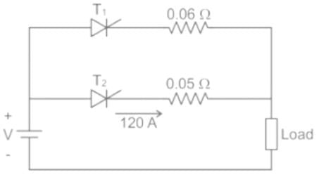
The figure below shows two thyristors each rated 500 A (continuous) sharing a load current. current through thyristor T2 is 120 A the current through T1 will be nearly equal to ___ (in A)
Correct answer is '100'. Can you explain this answer?
The figure below shows two thyristors each rated 500 A (continuous) sharing a load current. current through thyristor T2 is 120 A the current through T1 will be nearly equal to ___ (in A)

|
Pioneer Academy answered |
Concept
Matched-pair SCR’s are generally available for parallel connection, but they are very expensive. With unmatched SCR’s equal current sharing is enforced by adding a low-value resistor or inductor in series with each SCR. Forced current sharing using equal-value resistors is shown in Figure 2. The basic requirement is to make current I1 close to l2, a maximum difference of 20% is accept across SCR2, the value of R can be obtained from.
I1R + V1 = I2R + V2
I1R + V1 = I2R + V2
R = (V1 – V2)/(I2 – I1)
Calculation:
Voltage across 0.05 ohm resistor = 120 × 0.05 = 6 V
⇒ I2 = 6/0.06 = 100 A
Current through T1 will be nearly equal to 100 A
⇒ I2 = 6/0.06 = 100 A
Current through T1 will be nearly equal to 100 A
In case of an RC half wave triggering circuit, the firing angle can be ideally varied between- a)0 to 180
- b)0 to 90
- c)0 to 120
- d)0 to 360
Correct answer is option 'A'. Can you explain this answer?
In case of an RC half wave triggering circuit, the firing angle can be ideally varied between
a)
0 to 180
b)
0 to 90
c)
0 to 120
d)
0 to 360
|
|
Snehal Rane answered |
Unlike the R firing circuit, the RC firing circuits can be used to obtain firing angle greater than 180. Although practically 0 and 180 degree is improbable.
Consider the following devices:
1. TRIAC
2. GTO
3. BJT
4. MOSFET
5. DIAC
Which of these devices does not belong to the family of thyristors?- a)1 and 2 only
- b)3 and 4 only
- c)1, 2, 3, 4 and 5
- d)3, 4 and 5 only
Correct answer is option 'B'. Can you explain this answer?
Consider the following devices:
1. TRIAC
2. GTO
3. BJT
4. MOSFET
5. DIAC
Which of these devices does not belong to the family of thyristors?
1. TRIAC
2. GTO
3. BJT
4. MOSFET
5. DIAC
Which of these devices does not belong to the family of thyristors?
a)
1 and 2 only
b)
3 and 4 only
c)
1, 2, 3, 4 and 5
d)
3, 4 and 5 only
|
|
Samarth Khanna answered |
Introduction:
In electrical engineering, thyristors are a family of semiconductor devices that exhibit bistable behavior. Thyristors are widely used in various applications such as power control, motor control, and electronic switching. This question asks us to identify the device that does not belong to the family of thyristors among TRIAC, GTO, BJT, MOSFET, and DIAC.
Explanation:
Here, we will discuss each device and its characteristics to determine whether it belongs to the thyristor family or not.
1. TRIAC:
- TRIAC is a bidirectional device that can conduct current in both directions.
- It is a member of the thyristor family and is commonly used for AC power control applications.
- TRIACs are widely used in dimmer switches, motor speed control, and light dimming applications.
2. GTO (Gate Turn-Off Thyristor):
- GTO is a type of thyristor that can be turned off by applying a negative voltage to its gate terminal.
- It is a member of the thyristor family and is commonly used in high-power applications.
- GTOs are used in high-power inverters, motor drives, and traction systems.
3. BJT (Bipolar Junction Transistor):
- BJT is a three-layer semiconductor device that can amplify or switch electronic signals and power.
- It is not a member of the thyristor family.
- BJTs are commonly used in amplifiers, switches, and digital logic circuits.
4. MOSFET (Metal-Oxide-Semiconductor Field-Effect Transistor):
- MOSFET is a type of field-effect transistor that uses an insulated gate to control the flow of current.
- It is not a member of the thyristor family.
- MOSFETs are widely used in power amplifiers, switching regulators, and digital circuits.
5. DIAC (Diode Alternating Current):
- DIAC is a two-terminal device that can switch AC current in both directions.
- It is not a member of the thyristor family.
- DIACs are commonly used in triggering TRIACs and other thyristor-based devices.
Conclusion:
Based on the characteristics and properties of each device, we can conclude that the BJT (Bipolar Junction Transistor) and MOSFET (Metal-Oxide-Semiconductor Field-Effect Transistor) do not belong to the family of thyristors. Therefore, the correct answer is option 'b) 3 and 4 only'.
The decaying factor in the wave shape of the output pulses from the pulse transformer is its- a)transformer ratio
- b)inductance
- c)capacitance
- d)resistance
Correct answer is option 'B'. Can you explain this answer?
The decaying factor in the wave shape of the output pulses from the pulse transformer is its
a)
transformer ratio
b)
inductance
c)
capacitance
d)
resistance
|
|
Prisha Sengupta answered |
L is the decaying factor in the waveform which emerge from the PT.
The thyristor turn-off requires that the anode current- a)falls below the holding current
- b)falls below the latching current
- c)rises above the holding current
- d)rises above the latching current
Correct answer is option 'A'. Can you explain this answer?
The thyristor turn-off requires that the anode current
a)
falls below the holding current
b)
falls below the latching current
c)
rises above the holding current
d)
rises above the latching current
|
|
Jaya Dasgupta answered |
For effective turn-off of the SCR the anode current must fall below the holding current value.
Find the triggering frequency when the average gate power dissipation = 0.3 W and the peak gate drive power is 5 Watts. The gate source has a pulse width of 20 μsec duration.- a)3 kHz
- b)0.3 kHz
- c)30 kHz
- d)0.03 mHz
Correct answer is option 'A'. Can you explain this answer?
Find the triggering frequency when the average gate power dissipation = 0.3 W and the peak gate drive power is 5 Watts. The gate source has a pulse width of 20 μsec duration.
a)
3 kHz
b)
0.3 kHz
c)
30 kHz
d)
0.03 mHz
|
|
Srestha Gupta answered |
(Pgm) = (Pgav)/Duty Cycle
Duty Cycle = f x T = (Pgav)/(Pgm)
Duty Cycle = 0.3/5
T = 20 μsec.
0.3/5 = f x T
f = (0.3)/(5 x 20 x 10-6) = 3000 Hz.
Duty Cycle = f x T = (Pgav)/(Pgm)
Duty Cycle = 0.3/5
T = 20 μsec.
0.3/5 = f x T
f = (0.3)/(5 x 20 x 10-6) = 3000 Hz.
Which of the following is NOT an advantage of SCR as a switch?- a)The switching speed is very high.
- b)The operation does not produce harmonics.
- c)It gives noiseless operation at high efficiency.
- d)It has no moving parts.
Correct answer is option 'A'. Can you explain this answer?
Which of the following is NOT an advantage of SCR as a switch?
a)
The switching speed is very high.
b)
The operation does not produce harmonics.
c)
It gives noiseless operation at high efficiency.
d)
It has no moving parts.
|
|
Pooja Patel answered |
Advantages of SCR:
- It can handle large voltages, currents, and power.
- The voltage drop across conducting SCR is small. This will reduce the power dissipation in the SCR.
- Easy to turn on.
- The operation does not produce harmonics.
- Triggering circuits are simple.
- It has no moving parts.
- It gives noiseless operation at high efficiency.
- We can control the power delivered to the load.
Drawbacks of SCR:
- It can conduct only in one direction. So it can control power only during the one-half cycle of ac.
- It can turn on accidentally due to the high dv/dt of the source voltage.
- It is not easy to turn off the conducting SCR. We have to use special circuits called commutation circuits to turn off a conducting SCR.
- SCR cannot be used at high frequencies or perform high-speed operations. The maximum frequency of its operation is 400 Hz.
- Gate current cannot be negative.
Applications of SCR: Controlled rectifiers, DC to DC converters or choppers, DC to AC converters or inverters, As a static switch, Battery chargers, Speed control of DC and AC motors, Lamp dimmers, fan speed regulators, AC voltage stabilizers.
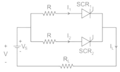
Assertion (A) : If the one-state anode current drops below a minimum level, designated as the holding current IH, the thyristor reverts to the forward blocking state.
Reason (R) : The loop gain of the equivalent pnp-npn transistors fall below unity and the regenerative hold-on action ceases.- a)Both A and R are true and R is the correct explanation of A.
- b)Both A and R are true but R is not the correct explanation of A.
- c)A is true but R is false.
- d)A is false but R is true.
Correct answer is option 'A'. Can you explain this answer?
Assertion (A) : If the one-state anode current drops below a minimum level, designated as the holding current IH, the thyristor reverts to the forward blocking state.
Reason (R) : The loop gain of the equivalent pnp-npn transistors fall below unity and the regenerative hold-on action ceases.
Reason (R) : The loop gain of the equivalent pnp-npn transistors fall below unity and the regenerative hold-on action ceases.
a)
Both A and R are true and R is the correct explanation of A.
b)
Both A and R are true but R is not the correct explanation of A.
c)
A is true but R is false.
d)
A is false but R is true.
|
|
Luminary Institute answered |
For successful turn ON i1 + i2 ≥ 100 mA
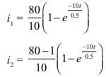
I = i1 + i2 = (8 + 7.9) (1 - e-20t ) = 100 mA
1 – e-20t = 6.30μ
t = 3.15 × 10⁻⁴ s
I = i1 + i2 = (8 + 7.9) (1 - e-20t ) = 100 mA
1 – e-20t = 6.30μ
t = 3.15 × 10⁻⁴ s
Thyristor is not made using germanium, because- a)its current handling capacity is less than silicon.
- b)it is a stable semiconductor.
- c)it has high leakage current.
- d)group V elements cannot be doped with it.
Correct answer is option 'C'. Can you explain this answer?
Thyristor is not made using germanium, because
a)
its current handling capacity is less than silicon.
b)
it is a stable semiconductor.
c)
it has high leakage current.
d)
group V elements cannot be doped with it.
|
|
Jaya Dasgupta answered |
The leakage current in silicon is of the order of nA while in Germanium it is in μA.
How many terminals are in DIAC ?- a)1
- b)4
- c)3
- d)2
Correct answer is option 'D'. Can you explain this answer?
How many terminals are in DIAC ?
a)
1
b)
4
c)
3
d)
2
|
|
Pooja Patel answered |
he DIAC is a 2-terminal semiconductor device and may be considered equivalent to two diodes connected in antiparallel.
A 300 A thyristor is to be operated in parallel with a 400 A thyristor their on state voltage drops are 1.8 V and 1 V respectively. The resistance to be connected in series with each thyristor so that the current through the combination is 700 A and each of them is fully loaded is ___________(in mΩ)
Correct answer is '8'. Can you explain this answer?
A 300 A thyristor is to be operated in parallel with a 400 A thyristor their on state voltage drops are 1.8 V and 1 V respectively. The resistance to be connected in series with each thyristor so that the current through the combination is 700 A and each of them is fully loaded is ___________(in mΩ)
|
|
Pooja Patel answered |
Concept
Matched-pair SCR’s are generally available for parallel connection, but they are very expensive. With unmatched SCR’s equal current sharing is enforced by adding a low-value resistor or inductor in series with each SCR. Forced current sharing using equal-value resistors is shown in Figure 2. The basic requirement is to make current I1 close to l2, a maximum difference of 20% is accept across SCR2, the value of R can be obtained from.
I1R + V1 = I2R + V2
I1R + V1 = I2R + V2
R = (V1 – V2)/(I2 – I1)
Calculation:
In parallel anode to cathode voltage drops are same
1.8 + 300 R = 1.0 + 400 R
⇒ 100 R = 0.8
⇒ R = 0.008 = 8 mΩ
The advantage of using a freewheeling diode with bridge type ac to dc converter is- a)reliable speed control
- b)reduced cost of system
- c)regenerative braking
- d)improved input power factor
Correct answer is option 'D'. Can you explain this answer?
The advantage of using a freewheeling diode with bridge type ac to dc converter is
a)
reliable speed control
b)
reduced cost of system
c)
regenerative braking
d)
improved input power factor
|
|
Gargi Mishra answered |
Advantage of using a freewheeling diode with a bridge type AC to DC converter is improved input power factor.
Explanation:
Bridge type AC to DC converter is used for converting AC voltage to DC voltage. However, it produces a pulsating DC voltage which is not suitable for most electronic devices. To smooth out the pulsations, a filter capacitor is used. But during the off time of the AC input voltage, the filter capacitor discharges through the load. This causes a reverse voltage across the diodes which can damage them.
To prevent this, a freewheeling diode is connected in parallel with each diode. During the off time of the AC input voltage, the freewheeling diode provides a path for the filter capacitor to discharge through the load. This prevents the reverse voltage across the diodes and protects them.
Moreover, the freewheeling diode also improves the input power factor by providing a path for the inductive load current to flow during the off time of the AC input voltage. This reduces the reactive power and improves the power factor.
Therefore, the advantage of using a freewheeling diode with a bridge type AC to DC converter is improved input power factor.
A four quadrant operation requires- a)two full converters connected back to back
- b)two full converters is series
- c)two semi-converters connected back to back
- d)two full converters connected in parallel
Correct answer is option 'C'. Can you explain this answer?
A four quadrant operation requires
a)
two full converters connected back to back
b)
two full converters is series
c)
two semi-converters connected back to back
d)
two full converters connected in parallel
|
|
Alok Verma answered |
In case “four quadrant operation" is required without any mechanical changeover switch, two full converters can be connected back to back to the load circuit. Such an arrangement using two converters in antiparailel and connected to the same dc load is called a “dual converter."
Parallel-capacitor commutation is- a)line commutation
- b)load commutation
- c)forced commutation
- d)external-pulse commutation
Correct answer is option 'C'. Can you explain this answer?
Parallel-capacitor commutation is
a)
line commutation
b)
load commutation
c)
forced commutation
d)
external-pulse commutation
|
|
Isha Singh answered |
Parallel capacitor is another name for forced commutation.
Assertion (A) : By using freewheeling diode, load performance becomes better.
Reason ( R ) : Freewheeling diode prevents the load voltage from becoming negative.- a)Both A and R are true and R is the correct explanation of A.
- b)Both A and R are true but R is not the correct explanation of A.
- c)A is true but R is false.
- d)A is false but R is true.
Correct answer is option 'B'. Can you explain this answer?
Assertion (A) : By using freewheeling diode, load performance becomes better.
Reason ( R ) : Freewheeling diode prevents the load voltage from becoming negative.
Reason ( R ) : Freewheeling diode prevents the load voltage from becoming negative.
a)
Both A and R are true and R is the correct explanation of A.
b)
Both A and R are true but R is not the correct explanation of A.
c)
A is true but R is false.
d)
A is false but R is true.
|
|
Prasad Saini answered |
By using freewheeling diode, load performance becomes better because load current waveform is improved.
Whenever load voltage tends to go negative, freewheeling comes into play as a result of which ioaa current is transferred from main thyristor to freewheeling diode, allowing the thyristor to regain its forward blocking capability.
Hence, both assertion and reason are true but reason is not the correct explanation of assertion.
The type of commutation when the load is commutated by transferring its load current to another incoming thyristor is- a)class A or load commutation
- b)class B or resonant commutation
- c)class C or complementary commutation
- d)class D or impulse commutation
Correct answer is option 'C'. Can you explain this answer?
The type of commutation when the load is commutated by transferring its load current to another incoming thyristor is
a)
class A or load commutation
b)
class B or resonant commutation
c)
class C or complementary commutation
d)
class D or impulse commutation
|
|
Bibek Saha answered |
In the Class C type commutation also called as complementary commutation the load is commutated by transferring the current th another device.
For an RC full wave firing circuit the empirical formula for calculating the value of RC is- a)RC = 157/ω
- b)RC = 157 x ω
- c)RC = ω/157
- d)RC = 157 x ω2
Correct answer is option 'A'. Can you explain this answer?
For an RC full wave firing circuit the empirical formula for calculating the value of RC is
a)
RC = 157/ω
b)
RC = 157 x ω
c)
RC = ω/157
d)
RC = 157 x ω2
|
|
Prisha Sen answered |
RC = 157/ω, Where ω is the angular frequency.
Consider the following statements:
1. In a full converter, direction of current cannot reverse.
2. Semi-converters are single quadrant converters.
3. A full converter can operate as a two-quadrant converter.
4. A full converter operates as a rectifier in first quadrant and as an inverter in the second quadrant.
5. In a full converter, direction of current cannot reverse but polarity of output voltage can be reversed.Q. Which of the statements given above are correct?- a)1, 2, 3 and 5
- b)2, 3 and 4
- c)2, 4 and 5
- d)1,3 and 4
Correct answer is option 'A'. Can you explain this answer?
Consider the following statements:
1. In a full converter, direction of current cannot reverse.
2. Semi-converters are single quadrant converters.
3. A full converter can operate as a two-quadrant converter.
4. A full converter operates as a rectifier in first quadrant and as an inverter in the second quadrant.
5. In a full converter, direction of current cannot reverse but polarity of output voltage can be reversed.
Q. Which of the statements given above are correct?
a)
1, 2, 3 and 5
b)
2, 3 and 4
c)
2, 4 and 5
d)
1,3 and 4
|
|
Arindam Sengupta answered |
Correct answer:
a)1, 2, 3 and 5
Explanation:
Full converters are AC to DC converters that have the ability to change the direction of current as well as the polarity of output voltage. Semi-converters, on the other hand, can only operate in one quadrant. The given statements can be explained as follows:
1. In a full converter, direction of current cannot reverse: This statement is incorrect. The direction of current in a full converter can be reversed by changing the firing angle of the thyristors.
2. Semi-converters are single quadrant converters: This statement is correct. Semi-converters can only operate in the first or third quadrant of the voltage-current plane.
3. A full converter can operate as a two-quadrant converter: This statement is correct. Full converters can operate in the first and fourth or second and third quadrants of the voltage-current plane.
4. A full converter operates as a rectifier in first quadrant and as an inverter in the second quadrant: This statement is incorrect. A full converter can operate as a rectifier or an inverter in any quadrant depending on the direction of current flow.
5. In a full converter, direction of current cannot reverse but polarity of output voltage can be reversed: This statement is correct. The direction of current can be changed by changing the firing angle of the thyristors but the polarity of output voltage can be reversed by changing the polarity of the DC source.
Therefore, the correct statements are 1, 2, 3, and 5.
The diode in the R firing circuit- a)ensures that the gate voltage is a half wave DC pulse
- b)ensures that the gate voltage is a full wave DC pulse
- c)ensures that the gate voltage is a half wave AC pulse
- d)ensures that the gate voltage is a full wave AC pulse
Correct answer is option 'B'. Can you explain this answer?
The diode in the R firing circuit
a)
ensures that the gate voltage is a half wave DC pulse
b)
ensures that the gate voltage is a full wave DC pulse
c)
ensures that the gate voltage is a half wave AC pulse
d)
ensures that the gate voltage is a full wave AC pulse
|
|
Sanskriti Bajaj answered |
The diode is placed between the resistances and gate which ensures that the current flows in one direction only.
Turn-on time (ton) of an SCR is related to its turn-off time (toff) in which of the following way?- a)ton < toff
- b)ton > toff
- c)toff increases with ton
- d)ton depends on L/R ratio of load
Correct answer is option 'D'. Can you explain this answer?
Turn-on time (ton) of an SCR is related to its turn-off time (toff) in which of the following way?
a)
ton < toff
b)
ton > toff
c)
toff increases with ton
d)
ton depends on L/R ratio of load
|
|
Kajal Mukherjee answered |
The turn-on time of an SCR depends on time constant (L/R) of the load.
A transformer is having source voltage of 400 volt and turns ratio of 2:1. The transformer is centre-tapped. If the secondary is connected to single phase full-wave converter, PIV per SCR will be- a)200√2 V
- b)100√2 V
- c)200 V
- d) 100 V
Correct answer is option 'A'. Can you explain this answer?
A transformer is having source voltage of 400 volt and turns ratio of 2:1. The transformer is centre-tapped. If the secondary is connected to single phase full-wave converter, PIV per SCR will be
a)
200√2 V
b)
100√2 V
c)
200 V
d)
100 V
|
|
Akanksha Chopra answered |
Secondary voltage = 
∴ PIV = 200√2 V
∴ PIV = 200√2 V
In a resistance firing circuit the firing angle- a)cannot be greater than 120°
- b)cannot be greater than 90°
- c)cannot be greater than 180°
- d)cannot be greater than 160°
Correct answer is option 'B'. Can you explain this answer?
In a resistance firing circuit the firing angle
a)
cannot be greater than 120°
b)
cannot be greater than 90°
c)
cannot be greater than 180°
d)
cannot be greater than 160°
|
|
Sakshi Roy answered |
The R firing circuits cannot be used for alpha greater than 90 degrees.
Chapter doubts & questions for Thyristors - Power Electronics 2025 is part of Electrical Engineering (EE) exam preparation. The chapters have been prepared according to the Electrical Engineering (EE) exam syllabus. The Chapter doubts & questions, notes, tests & MCQs are made for Electrical Engineering (EE) 2025 Exam. Find important definitions, questions, notes, meanings, examples, exercises, MCQs and online tests here.
Chapter doubts & questions of Thyristors - Power Electronics in English & Hindi are available as part of Electrical Engineering (EE) exam.
Download more important topics, notes, lectures and mock test series for Electrical Engineering (EE) Exam by signing up for free.
Power Electronics
5 videos|67 docs|46 tests
|
|
© EduRev
|
Education Revolution
|


|


Signup on EduRev and stay on top of your study goals
10M+ students crushing their study goals daily