


All Exams >
Electrical Engineering (EE) >
Power Electronics >
All Questions
All questions of Choppers for Electrical Engineering (EE) Exam
If T is the chopping period, Ton the on-time period of chopper and Toff the off-time period of the chopper, then consider the following statements associated with the methods of controlling the output voltage of a chopper:
1. In pulse-width modulation (PWM) scheme, T is kept constant while Ton is varied.
2. In variable-frequency modulation (VFM) scheme, T is varied while either of Ton or Toff is kept constant.
3. In PWM scheme, the output voltage can be varied between zero to source voltage.
4. The large Toff in VFM scheme may make the load current discontinuous
5. PWM scheme is better than VFM scheme.Which of the statements given above are correct?- a)1,2,3, 4, and 5
- b)2, 3 and 5
- c)1,3 and 4
- d)2, 3, 4 and 5
Correct answer is option 'A'. Can you explain this answer?
If T is the chopping period, Ton the on-time period of chopper and Toff the off-time period of the chopper, then consider the following statements associated with the methods of controlling the output voltage of a chopper:
1. In pulse-width modulation (PWM) scheme, T is kept constant while Ton is varied.
2. In variable-frequency modulation (VFM) scheme, T is varied while either of Ton or Toff is kept constant.
3. In PWM scheme, the output voltage can be varied between zero to source voltage.
4. The large Toff in VFM scheme may make the load current discontinuous
5. PWM scheme is better than VFM scheme.
Which of the statements given above are correct?
a)
1,2,3, 4, and 5
b)
2, 3 and 5
c)
1,3 and 4
d)
2, 3, 4 and 5
|
|
Luminary Institute answered |
For dc – dc converter the critical inductance value.
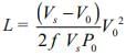
V0 = a Vs = 0.8 × 100 = 80 V
I0 = 2A Power P0 = V0 I0 = 160 Watt
f = 500
= 8 × 10⁻³ H = 8 mH.
V0 = a Vs = 0.8 × 100 = 80 V
I0 = 2A Power P0 = V0 I0 = 160 Watt
f = 500
= 8 × 10⁻³ H = 8 mH.

In dc choppers, the waveforms for input and output voltages are respectively- a)continuous, discontinuous
- b)both discontinuous
- c)discontinuous, continuous
- d)both continuous
Correct answer is option 'A'. Can you explain this answer?
In dc choppers, the waveforms for input and output voltages are respectively
a)
continuous, discontinuous
b)
both discontinuous
c)
discontinuous, continuous
d)
both continuous
|
|
Prisha Sengupta answered |
Explanation:
DC choppers are electronic devices that are used to convert a fixed DC voltage into a variable DC voltage. The waveform for input and output voltages in DC choppers is as follows:
Input Voltage Waveform:
The input voltage waveform is continuous in DC choppers. It means that the voltage is present at the input of the chopper throughout the operation.
Output Voltage Waveform:
The output voltage waveform is discontinuous in DC choppers. It means that the output voltage is present only for a certain period of time during the operation.
Reason:
The reason for the continuous input voltage waveform is that the input voltage is connected to a DC source that provides a constant voltage. On the other hand, the output voltage waveform is discontinuous because the chopper switches ON and OFF at a certain frequency. During the ON state, the output voltage is present, and during the OFF state, the output voltage is not present.
Conclusion:
Hence, we can conclude that the waveforms for input and output voltages in DC choppers are respectively continuous and discontinuous.
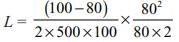
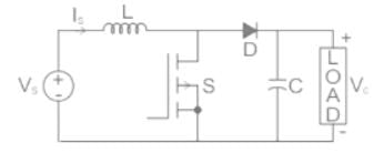
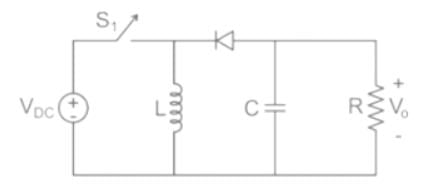
In the circuit shown below, if load R = 500 Ω, switching frequency is 25 kHz and peak to peak ripple current of inductor is limited to 0.9 A then the filter inductance L is

- a)111.62 μH
- b)115.83 μH
- c)136.24 μH
- d)129.62 μH
Correct answer is option 'D'. Can you explain this answer?
In the circuit shown below, if load R = 500 Ω, switching frequency is 25 kHz and peak to peak ripple current of inductor is limited to 0.9 A then the filter inductance L is
a)
111.62 μH
b)
115.83 μH
c)
136.24 μH
d)
129.62 μH
|
|
Luminary Institute answered |
For Buck Converter
The peak to peak ripple current is
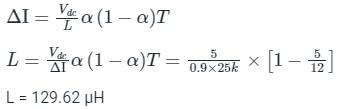
The peak to peak ripple current is
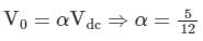
A 220 V dc shunt motor runs at 1500 rpm at no-load. The motor is fed through a type-A chopper. If the armature resistance is 1 Ω and duty cycle of chopper is 60%, the speed of the motor when it draw a current of 20 A would be approximately equal to- a)636 rpm
- b)842 rpm
- c)764 rpm
- d)535 rpm
Correct answer is option 'C'. Can you explain this answer?
A 220 V dc shunt motor runs at 1500 rpm at no-load. The motor is fed through a type-A chopper. If the armature resistance is 1 Ω and duty cycle of chopper is 60%, the speed of the motor when it draw a current of 20 A would be approximately equal to
a)
636 rpm
b)
842 rpm
c)
764 rpm
d)
535 rpm
|
|
Aashna Dey answered |
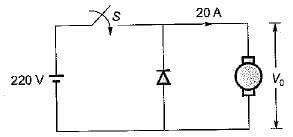
The output voltage,
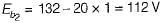
V0 = αVs = 0.6 x 220 - 132 V
∴ Back emf
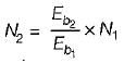
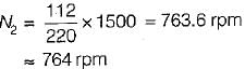
At no- load, N1, = 1500 rpm and Eb1 = 220 V Now, Eb α N
∴

or,
or,
A d.c. chopper circuit connected to a 100 V d.c. source supplies an inductive load having 40 mH in series with a resistance of 5 Ω A freewheeling diode is placed across the load. The load current varies between the limits of 10 A and 12 A. The time ratio (Ton/Toff) of the chopper is- a)1.65
- b)0.98
- c)1.22
- d)0.75
Correct answer is option 'C'. Can you explain this answer?
A d.c. chopper circuit connected to a 100 V d.c. source supplies an inductive load having 40 mH in series with a resistance of 5 Ω A freewheeling diode is placed across the load. The load current varies between the limits of 10 A and 12 A. The time ratio (Ton/Toff) of the chopper is
a)
1.65
b)
0.98
c)
1.22
d)
0.75
|
|
Kiran Iyer answered |
The average value of load current
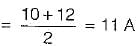
The maximum value of load current
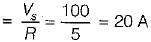
Now, the average value of the voltage is
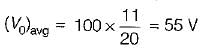
Also,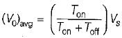
or,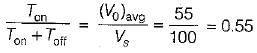
or,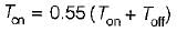
or,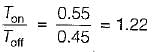
The maximum value of load current
Now, the average value of the voltage is
Also,
or,
or,
or,
In chopper circuit the average value of output voltage is controlled by time ratio control (TRC) method. The chopper is operated at a frequency of 5kHz on a 230 V d.c. supply. If the load voltage is 180 V, then the blocking period of thyristor in each cycle is___(in μsec)
Correct answer is between '43,44'. Can you explain this answer?
In chopper circuit the average value of output voltage is controlled by time ratio control (TRC) method. The chopper is operated at a frequency of 5kHz on a 230 V d.c. supply. If the load voltage is 180 V, then the blocking period of thyristor in each cycle is___(in μsec)
|
|
Pooja Patel answered |
Vo = Vdc × Ton × f
f = 5 kHz, Vdc = 230 V, Vo = 180
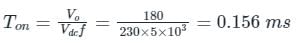
but chopping period
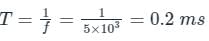
blocking period of SCR
Toff = T – Ton = 0.2 – 0.156 = 0.04347 msec = 43.47 μsec
f = 5 kHz, Vdc = 230 V, Vo = 180
but chopping period
blocking period of SCR
Toff = T – Ton = 0.2 – 0.156 = 0.04347 msec = 43.47 μsec
Assertion (A): The principal of step-up chopper can be employed for the regenerative braking of dc motors.
Reason (R) : The step-up chopper can be employed in regenerative braking only for increasing motor speeds- a)Both A and R are true and R is the correct explanation of A.
- b)Both A and R are true but R is not the correct explanation of A
- c)A is true but R is false
- d)A is false but R is true
Correct answer is option 'C'. Can you explain this answer?
Assertion (A): The principal of step-up chopper can be employed for the regenerative braking of dc motors.
Reason (R) : The step-up chopper can be employed in regenerative braking only for increasing motor speeds
Reason (R) : The step-up chopper can be employed in regenerative braking only for increasing motor speeds
a)
Both A and R are true and R is the correct explanation of A.
b)
Both A and R are true but R is not the correct explanation of A
c)
A is true but R is false
d)
A is false but R is true
|
|
Abhishek Chauhan answered |
The step-up chopper can be employed in regenerative braking both for increasing and decreasing motor speed provided duty cycle a is so adjusted that Vs/( 1 - a) exceeds the fixed source voiiage V0. Hence, reason is a false statement.
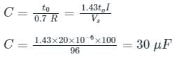
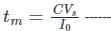
What value of capacitor (in μF) is required to forces commutate a thyristor with a turn off time of 20 μs with a 96 V battery and a full load current of 100 A.
Correct answer is between '28,32'. Can you explain this answer?
What value of capacitor (in μF) is required to forces commutate a thyristor with a turn off time of 20 μs with a 96 V battery and a full load current of 100 A.
|
|
Pooja Patel answered |
The size of capacitor enquired for commutation is
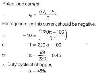
IA class C chopper is operated from a 220 V battery. The load Is a dc motor with R = 0.1Ω, L= 10 mH and Eb= 100 V. The duty cycle of the chopper to achieve regenerative braking at the rated current of 10 Ampere would be equal to- a)25%
- b)45%
- c)66%
- d)72%
Correct answer is option 'B'. Can you explain this answer?
IA class C chopper is operated from a 220 V battery. The load Is a dc motor with R = 0.1Ω, L= 10 mH and Eb= 100 V. The duty cycle of the chopper to achieve regenerative braking at the rated current of 10 Ampere would be equal to
a)
25%
b)
45%
c)
66%
d)
72%
|
|
Bhavana Reddy answered |
In dc choppers, per unit ripple is maximum when duty cycle α is- a)0.9
- b)0.7
- c)0.5
- d)0.2
Correct answer is option 'C'. Can you explain this answer?
In dc choppers, per unit ripple is maximum when duty cycle α is
a)
0.9
b)
0.7
c)
0.5
d)
0.2

|
EduRev GATE answered |
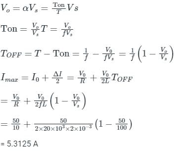
The minimum turn-ON time of the SCR is = 

For step down chopper, Vo = δ VS
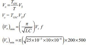
(Vo )min = 50 π V
For step down chopper, Vo = δ VS
(Vo )min = 50 π V
In a 110 V DC chopper drive using the CLC scheme, the maximum possible value of the accelerating current is 300 A. The lower limit of the current pulsation is 140 A. What is the maximum limit of current pulsation? - a)140 A
- b)440 A
- c)160 A
- d)150 A
Correct answer is option 'B'. Can you explain this answer?
In a 110 V DC chopper drive using the CLC scheme, the maximum possible value of the accelerating current is 300 A. The lower limit of the current pulsation is 140 A. What is the maximum limit of current pulsation?
a)
140 A
b)
440 A
c)
160 A
d)
150 A
|
|
Alok Khanna answered |
Introduction:
In a 110 V DC chopper drive using the CLC scheme, the maximum possible value of the accelerating current is given as 300 A, and the lower limit of the current pulsation is given as 140 A. We need to determine the maximum limit of the current pulsation.
Understanding the Chopper Drive:
A chopper drive is an electronic circuit that controls the speed and direction of a DC motor. It uses a chopper switch to control the average voltage applied to the motor, thereby controlling its speed. The CLC scheme stands for Constant Load Current scheme, which is a common control strategy used in chopper drives.
Calculating the Maximum Limit of Current Pulsation:
The current pulsation in a chopper drive is the difference between the maximum and minimum current levels. In this case, the maximum possible value of the accelerating current is given as 300 A, and the lower limit of the current pulsation is given as 140 A.
To calculate the maximum limit of current pulsation, we need to subtract the lower limit of current pulsation from the maximum possible value of the accelerating current:
Maximum limit of current pulsation = Maximum possible value of accelerating current - Lower limit of current pulsation
= 300 A - 140 A
= 160 A
Conclusion:
Therefore, the maximum limit of current pulsation in the given 110 V DC chopper drive using the CLC scheme is 160 A. Hence, option C (160 A) is the correct answer.
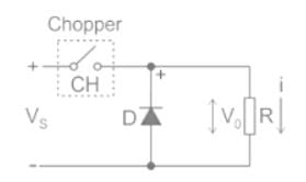
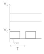
A step-up chopper is used to deliver a load voltage of 500 V from a 220 V d.c. source. If the blocking period of the thyristor is 80 μs, the required pulse width is -- a)50.8 μs
- b)101.8 μs
- c)92.4 μs
- d)152.4 μs
Correct answer is option 'B'. Can you explain this answer?
A step-up chopper is used to deliver a load voltage of 500 V from a 220 V d.c. source. If the blocking period of the thyristor is 80 μs, the required pulse width is -
a)
50.8 μs
b)
101.8 μs
c)
92.4 μs
d)
152.4 μs
|
|
Vibhor Goyal answered |
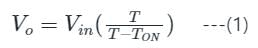
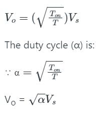
Concept:
The output voltage of a step-up chopper is given by:
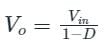
where, Vo = Output voltage
Vin = Input voltage
D = Duty cycle
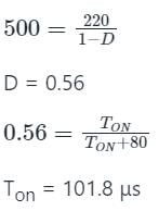
The duty cycle is given by:
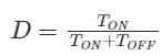
TON is the pulse width of the output.
Calculation:
Given, Vo = 500 V
Vin = 220 V
Toff = 80 μs
A buck converter has an input current of 2.4 A while required output current is 6 A. What will be the duty cycle of the converter? [Assume lossless system]- a)0.4
- b)1.0
- c)0.8
- d)2.0
Correct answer is option 'A'. Can you explain this answer?
A buck converter has an input current of 2.4 A while required output current is 6 A. What will be the duty cycle of the converter? [Assume lossless system]
a)
0.4
b)
1.0
c)
0.8
d)
2.0
|
|
Anjali Choudhury answered |
Calculation of Duty Cycle
To find the duty cycle of the buck converter, we can use the formula:
Duty Cycle = Output Voltage / Input Voltage
Given:
Input Current (Iin) = 2.4 A
Output Current (Iout) = 6 A
Calculating Duty Cycle:
Since the converter is lossless, the input power is equal to the output power.
Input Power = Output Power
Vin * Iin = Vout * Iout
We know that Vout = Duty Cycle * Vin
Therefore, Vin * Iin = (Duty Cycle * Vin) * Iout
Duty Cycle = (Iin / Iout) = 2.4 A / 6 A = 0.4
Therefore, the duty cycle of the buck converter is 0.4, which means the switch is ON 40% of the time during each switching cycle.
A four-quadrant chopper is driving a separately excited dc motor load. The motor parameters are R = 0.1 Ω, L = 10 mH. The supply voltage is 200 V d.c. If the rated current of the motor is 10 A with Eb = 150 V and motor is driving the rated torque, then it is operating under- a)forward motoring mode
- b)reverse braking mode
- c)reverse motoring mode
- d)forward brakina mode
Correct answer is option 'A'. Can you explain this answer?
A four-quadrant chopper is driving a separately excited dc motor load. The motor parameters are R = 0.1 Ω, L = 10 mH. The supply voltage is 200 V d.c. If the rated current of the motor is 10 A with Eb = 150 V and motor is driving the rated torque, then it is operating under
a)
forward motoring mode
b)
reverse braking mode
c)
reverse motoring mode
d)
forward brakina mode
|
|
Hiral Kulkarni answered |
For a four-quadrant chopper, the average voltage in all the four-modes is given by
V0 = 2 Vs (α - 0.5)
The average curreni,
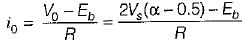
or,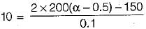
or, α = 0.877
Since α > 0.5, the motor is operating undi
forward motorina mode.
V0 = 2 Vs (α - 0.5)
The average curreni,
or,
or, α = 0.877
Since α > 0.5, the motor is operating undi
forward motorina mode.
Consider the boost converter of the input voltage to this converter is 6 V. The average output voltage is Vo = 18 V and the average load current Io = 0.4 A. If the switching frequency is 20 kHz for L = 250 μH, then the ripple current of inductor is _______A.- a)1 A
- b)2.5 A
- c)3 A
- d)0.8 A
Correct answer is option 'D'. Can you explain this answer?
Consider the boost converter of the input voltage to this converter is 6 V. The average output voltage is Vo = 18 V and the average load current Io = 0.4 A. If the switching frequency is 20 kHz for L = 250 μH, then the ripple current of inductor is _______A.
a)
1 A
b)
2.5 A
c)
3 A
d)
0.8 A
|
|
Sparsh Saini answered |
To find the inductor value (L) for the boost converter, we can use the following equation:
L = (Vo * (Vin - Vo)) / (Vin * F * Io)
where:
Vo = average output voltage = 18 V
Vin = input voltage = 6 V
F = switching frequency = 20 kHz
Io = average load current = 0.4 A
Plugging in the given values:
L = (18 * (6 - 18)) / (6 * 20,000 * 0.4)
L = (-180) / (4,800)
L = -0.0375 H
However, it is not physically possible to have a negative inductance value. Therefore, there may be an error in the given values or calculation. Please double-check the values and provide the correct information for a valid calculation.
A step-up chopper is fed with 200 V. The conduction time of the thyristor is 200 µs and the required output is 600 V. If the frequency of operation is kept constant and the pulse width is halved, what will be the new output voltage?- a)600 volts
- b)300 volts
- c)400 volts
- d)200 volts
Correct answer is option 'B'. Can you explain this answer?
A step-up chopper is fed with 200 V. The conduction time of the thyristor is 200 µs and the required output is 600 V. If the frequency of operation is kept constant and the pulse width is halved, what will be the new output voltage?
a)
600 volts
b)
300 volts
c)
400 volts
d)
200 volts
|
|
Vibhor Goyal answered |
Formula:
Where, Vo is the output voltage
Vin is the input voltage
TON is the pulse width
Application:
Given,
Vin = 200 volts
TON = 200 µs
V0 = 600 V
From equation (1),
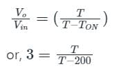
or, 3T - 600 = T
Hence, T = 300 µs
If the Pulse width is half then, the new value of pulse width (TON') will be,
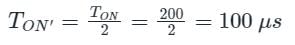
Hence,
Hence, the new value of output voltage (V0') will be,

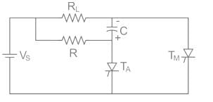
Consider the circuit shown below:
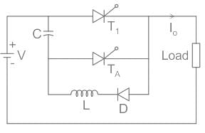
The effective on period of the chopper if V =230 V,Io = 60 A,C = 55 μF,Ton = 800 μs is:- a)1.22 ms
- b)1.07 ms
- c)1.85 ms
- d)1.47 ms
Correct answer is option 'A'. Can you explain this answer?
Consider the circuit shown below:
The effective on period of the chopper if V =230 V,Io = 60 A,C = 55 μF,Ton = 800 μs is:
The effective on period of the chopper if V =230 V,Io = 60 A,C = 55 μF,Ton = 800 μs is:
a)
1.22 ms
b)
1.07 ms
c)
1.85 ms
d)
1.47 ms

|
Naroj Boda answered |
Concept:
Mode 1: T1 will remain ON and conduct to load and diode TA will remain OFF
Mode 2: TA will be turned ON; the capacitor current will now flow in reverse direction & T1 stops conducting.
Therefore, the effective time period of the chopper is
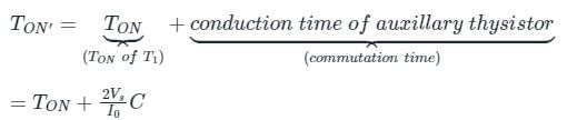
Commutation time: It is the time taken to disconnect the load from the supply after the main thyristor is turned OFF.
Calculation:
Effective on period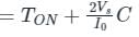
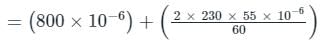
= (0.8 + 0.42) × 10-3
TON’ = 1.22 ms
Mode 1: T1 will remain ON and conduct to load and diode TA will remain OFF
Mode 2: TA will be turned ON; the capacitor current will now flow in reverse direction & T1 stops conducting.
Therefore, the effective time period of the chopper is
Commutation time: It is the time taken to disconnect the load from the supply after the main thyristor is turned OFF.
Calculation:
Effective on period
= (0.8 + 0.42) × 10-3
TON’ = 1.22 ms
A dc chopper is fed from constant voltage mains. The duty ratio α of the chopper is progressively increased while the chopper feeds RL load. The per unit current ripple would- a)Increase progressively.
- b)Decrease progressively.
- c)Decrease to a minimum value at α = 0.5 and then increase.
- d)Increase to a maximum value at α = 0.5 and then decrease.
Correct answer is option 'D'. Can you explain this answer?
A dc chopper is fed from constant voltage mains. The duty ratio α of the chopper is progressively increased while the chopper feeds RL load. The per unit current ripple would
a)
Increase progressively.
b)
Decrease progressively.
c)
Decrease to a minimum value at α = 0.5 and then increase.
d)
Increase to a maximum value at α = 0.5 and then decrease.
|
|
Pooja Patel answered |
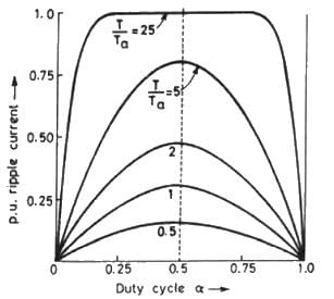
Ripple current in the chopper circuit :
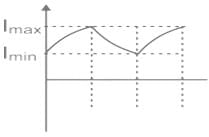
Ripple current is the difference between maximum current (Imx) and minimum current (Imin) flowing through the chopper circuit in the steady-state operation of the chopper.
The ripple current of chopper operating in steady-state is given by
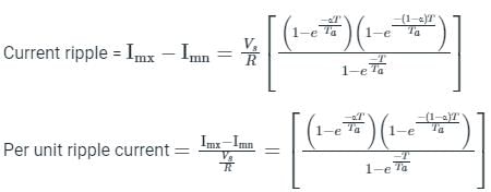
Where
α = duty cycle of the chopper, Vs = DC supply voltage, R = load resistance, Ta = time constant = L/R , and T = time period of the chopper
From the above equation, we can observe per unit ripple current is only depends on the time constant (Ta), Time period (T), and duty cycle (α ).
Variation of ripple current with a duty cycle (α) and T/Ta ratio:
We can observe the variation of ripple current with duty cycle and T/Ta ration in the figure is shown below,
Ripple current is the difference between maximum current (Imx) and minimum current (Imin) flowing through the chopper circuit in the steady-state operation of the chopper.
The ripple current of chopper operating in steady-state is given by
Where
α = duty cycle of the chopper, Vs = DC supply voltage, R = load resistance, Ta = time constant = L/R , and T = time period of the chopper
From the above equation, we can observe per unit ripple current is only depends on the time constant (Ta), Time period (T), and duty cycle (α ).
Variation of ripple current with a duty cycle (α) and T/Ta ratio:
We can observe the variation of ripple current with duty cycle and T/Ta ration in the figure is shown below,
- From the above graph, the value of ripple current is increased with an increasing duty cycle (α) up to some instant where the value of α =0.5, and after that, it is decreasing.
- The maximum value of ripple current is given at the value of α = 0.5
- The maximum value of the ripple current is increased with increasing T/Ta ratio but still, the max ripple current occurs at α = 0.5.
A single-quadrant type A chopper is operating with the following specifications:
Ideal battery of 220 V;
on-time ton - 1 ms;
off-time foff = 1.5 ms
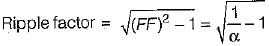
The ripple and form factors will be respectively given by- a)0.98 and 1.20
- b)1.58 and 1.22
- c)1.22 and 1.58
- d)1.58 and 1.20
Correct answer is option 'C'. Can you explain this answer?
A single-quadrant type A chopper is operating with the following specifications:
Ideal battery of 220 V;
on-time ton - 1 ms;
off-time foff = 1.5 ms
The ripple and form factors will be respectively given by
Ideal battery of 220 V;
on-time ton - 1 ms;
off-time foff = 1.5 ms
The ripple and form factors will be respectively given by
a)
0.98 and 1.20
b)
1.58 and 1.22
c)
1.22 and 1.58
d)
1.58 and 1.20
|
|
Juhi Joshi answered |
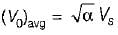
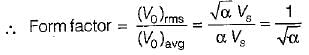
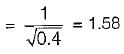
For a type-A chopper, average output voltage
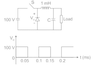
In the LC circuit shown in the figure initial current through the inductor is zero, initial voltage across the capacitor is 100 V. Switch S is closed at t = 0 sec. The current through the circuit is
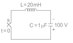
- a)7.07 sin (7.07 × 10³ t)
- b)0.707 cos (7.07 × 10³ t)
- c)0.707 sin (7.07 × 10³ t)
- d)7.07 cos (7.07 × 10³ t)
Correct answer is option 'C'. Can you explain this answer?
In the LC circuit shown in the figure initial current through the inductor is zero, initial voltage across the capacitor is 100 V. Switch S is closed at t = 0 sec. The current through the circuit is
a)
7.07 sin (7.07 × 10³ t)
b)
0.707 cos (7.07 × 10³ t)
c)
0.707 sin (7.07 × 10³ t)
d)
7.07 cos (7.07 × 10³ t)

|
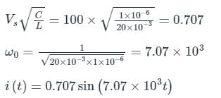
Pioneer Academy answered |
Concept:
In a LC circuit, the current flows in the circuit is given by,
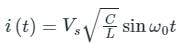
Where, VS is supply voltage in V
C is capacitance in F
L is inductance in H
ω0 is resonant frequency in rad/sec

Calculation:
From the given circuit, VS = 100 V
C = 1 μF
L = 20 mH
In a LC circuit, the current flows in the circuit is given by,
Where, VS is supply voltage in V
C is capacitance in F
L is inductance in H
ω0 is resonant frequency in rad/sec
Calculation:
From the given circuit, VS = 100 V
C = 1 μF
L = 20 mH
Assertion (A) : In dc choppers, it is essential to provide a separate commutation circuitry to commutate the main power SCR.
Reason ( R ) : A chopper is dc equivalent to an ac transformer having continuously variable turns ratio.- a)Both A and R are true and R is the correct explanation of A.
- b)Both A and R are true but R is not the correct explanation of A.
- c)A is true but R is false.
- d)A is false but R is true.
Correct answer is option 'B'. Can you explain this answer?
Assertion (A) : In dc choppers, it is essential to provide a separate commutation circuitry to commutate the main power SCR.
Reason ( R ) : A chopper is dc equivalent to an ac transformer having continuously variable turns ratio.
Reason ( R ) : A chopper is dc equivalent to an ac transformer having continuously variable turns ratio.
a)
Both A and R are true and R is the correct explanation of A.
b)
Both A and R are true but R is not the correct explanation of A.
c)
A is true but R is false.
d)
A is false but R is true.
|
|
Niharika Basu answered |
Since the input supply to a dc chopper is fixed do voltage therefore, natural commutation is not possible in a dc chopper. Due to this reason a separate commutation circuit is required to commutate the main power SCR in a dc chopper. Reason is also a true statement but not the correct explanation of assertion.
A buck converter is used to control a d.c. motor. The input to a dc buck converter is 200 V. Find the duty ratio of the pulse to be applied to the converter to produce 150 V across the d.c. motor.- a)60%
- b)50%
- c)35%
- d)75%
Correct answer is option 'D'. Can you explain this answer?
A buck converter is used to control a d.c. motor. The input to a dc buck converter is 200 V. Find the duty ratio of the pulse to be applied to the converter to produce 150 V across the d.c. motor.
a)
60%
b)
50%
c)
35%
d)
75%
|
|
Vibhor Goyal answered |
Concept:
In a buck converter (step down chopper)
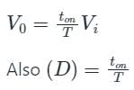
Where,
D = Duty ratio
V0 = Average out-put voltage or DC output voltage
Vi = Input voltage
ton = On time period
T = total time period
Calculation:
V0 = 150 V, Vi = 200 V
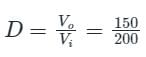
D = 0.75 = 75%
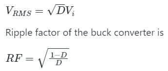
Note:
RMS output voltage of buck converter is given by
In the circuit shown in figure find the circuit turn off time is ______ μs
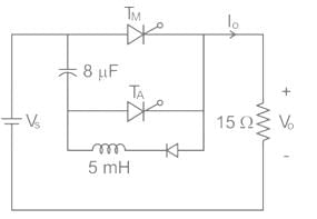
Correct answer is between '83,84'. Can you explain this answer?
In the circuit shown in figure find the circuit turn off time is ______ μs

|
Cstoppers Instructors answered |
In voltage commutation circuit
Circuit turn off time
 for highly inductive load
tm = RC ln 2 ------- for resistive load
∴ tm = 15 × 8 × 10-6 ln 2 = 83.18 μs
Circuit turn off time
for highly inductive loadtm = RC ln 2 ------- for resistive load
∴ tm = 15 × 8 × 10-6 ln 2 = 83.18 μs
For a step-down DC chopper with a resistive load, when the duty cycle is increased the average value of the output voltage-- a)Decreases
- b)Remains the same
- c)ls zero
- d)Increases
Correct answer is option 'D'. Can you explain this answer?
For a step-down DC chopper with a resistive load, when the duty cycle is increased the average value of the output voltage-
a)
Decreases
b)
Remains the same
c)
ls zero
d)
Increases
|
|
Ayush Kumar answered |
Explanation:
Step-down DC Chopper:
- A step-down DC chopper is a circuit that converts a high-voltage DC input to a lower-voltage DC output using a switching mechanism.
Resistive Load:
- In this case, the DC chopper is connected to a resistive load, which means that the load impedance is purely resistive.
Duty Cycle:
- The duty cycle of a chopper is the ratio of the on-time of the switch to the total period of the switch. It is usually expressed as a percentage.
Effect of Increasing Duty Cycle:
- When the duty cycle of a step-down DC chopper is increased, it means that the switch is on for a larger portion of the total period.
- This results in more energy being transferred to the load during each switching cycle.
- As a result, the average value of the output voltage increases because the load receives more energy over time.
Therefore, when the duty cycle is increased in a step-down DC chopper with a resistive load, the average value of the output voltage increases.
A step-up dc chopper has input dc voltage of 200 V and average output voltage 500 V. If the conduction time of the switch is 150 μs, determine the pulse width of the output voltage.- a)250 μs
- b)150 μs
- c)100 μs
- d)110 μs
Correct answer is option 'A'. Can you explain this answer?
A step-up dc chopper has input dc voltage of 200 V and average output voltage 500 V. If the conduction time of the switch is 150 μs, determine the pulse width of the output voltage.
a)
250 μs
b)
150 μs
c)
100 μs
d)
110 μs
|
|
Rajesh Saha answered |
Ms, what is the duty cycle of the chopper?
Duty cycle is defined as the ratio of the conduction time of the switch to the total time period.
Given:
Input DC voltage (Vin) = 200 V
Average output voltage (Vout) = 500 V
Conduction time of the switch = 150 ms
The duty cycle (D) can be calculated using the formula:
D = (T_on / T_total)
Where:
T_on = conduction time of the switch
T_total = total time period
Since the conduction time of the switch is given as 150 ms, we need to find the total time period.
The average output voltage can be expressed as:
Vout = D * Vin
Rearranging the equation to find D:
D = Vout / Vin
Substituting the given values:
D = 500 V / 200 V
D = 2.5
The duty cycle of the chopper is 2.5.
A boost-regulator has an input voltage of 5 V and the average output voltage of 15 V, The duty cycle is- a)3/2
- b)2/3
- c)5/2
- d)15/2
Correct answer is option 'B'. Can you explain this answer?
A boost-regulator has an input voltage of 5 V and the average output voltage of 15 V, The duty cycle is
a)
3/2
b)
2/3
c)
5/2
d)
15/2
|
|
Nishtha Chauhan answered |
Boost-regulator is a step-up chopper.
Output voltage,

or,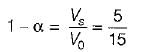
or,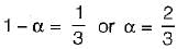
Output voltage,
or,
or,
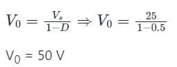
If the duty ratio of a boost converter is 50 percent, the output voltage corresponding to an input of 25 V is- a)50 V
- b)30 V
- c)40 V
- d)25 V
Correct answer is option 'A'. Can you explain this answer?
If the duty ratio of a boost converter is 50 percent, the output voltage corresponding to an input of 25 V is
a)
50 V
b)
30 V
c)
40 V
d)
25 V

|
Crack Gate answered |
Concept:
The circuit diagram of a boost converter is shown below.
Step Up or Boost converter is used to obtain the output voltage greater than the input voltage.
The relation between the output voltage and the input voltage is given by
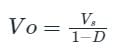
Where D is the duty cycle of the chopper
Calculation:
Duty ratio = 50 % = 0.5
Input voltage (VS) = 25 V
Average output voltage (Vo) =
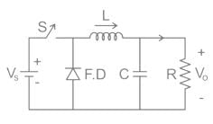
For the circuit shown in the figure, assume L to be large enough to ensure linear growth and decay of the current through it and have continuous current. The maximum value of the load current in amperes is _________ (Vs = 100 V, Vo = 50 V, L = 2mH, f = 20 kHz, R = 10 Ω)
Correct answer is between '5,6'. Can you explain this answer?
For the circuit shown in the figure, assume L to be large enough to ensure linear growth and decay of the current through it and have continuous current. The maximum value of the load current in amperes is _________ (Vs = 100 V, Vo = 50 V, L = 2mH, f = 20 kHz, R = 10 Ω)
|
|
Pioneer Academy answered |
The function of capacitor C across-load resistance R is to make the output voltage continuous.

If the motor in the previous problem is driven by an active load at 1710 rpm, then the type of chopper suitable for speed control and its duty cycle for an input voltage of 250 V will be respectively- a)first quadrant and 7.7%
- b)second quadrant and 6.5%
- c)first quadrant and 6.5%
- d)second quadrant and 7.7%
Correct answer is option 'D'. Can you explain this answer?
If the motor in the previous problem is driven by an active load at 1710 rpm, then the type of chopper suitable for speed control and its duty cycle for an input voltage of 250 V will be respectively
a)
first quadrant and 7.7%
b)
second quadrant and 6.5%
c)
first quadrant and 6.5%
d)
second quadrant and 7.7%
|
|
Upasana Joshi answered |
As the motor is running at 1710 rpm its back emf is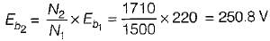
Since therefore current flows in the reverse direction and hence second quadrant chopper will be used with the motor.
Now,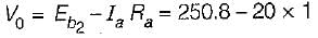
= 230.8 volt
Also, V0 = (1 - α) Vs
or, 230.8 = (1 - α) x 250
or, 1 - α = 0.9232 or α = 0.0768
or, α = 7.68% = 7.7%
Since
therefore current flows in the reverse direction and hence second quadrant chopper will be used with the motor.Now,
= 230.8 volt
Also, V0 = (1 - α) Vs
or, 230.8 = (1 - α) x 250
or, 1 - α = 0.9232 or α = 0.0768
or, α = 7.68% = 7.7%
The duty cycle of a step-down chopper is 55% and the value of the source voltage is 100 V. Find its output voltage.- a)45 V
- b)65 V
- c)50 V
- d)55 V
Correct answer is option 'D'. Can you explain this answer?
The duty cycle of a step-down chopper is 55% and the value of the source voltage is 100 V. Find its output voltage.
a)
45 V
b)
65 V
c)
50 V
d)
55 V
|
|
Raghav Nambiar answered |
Understanding Duty Cycle in Step-Down Chopper
In a step-down chopper, the duty cycle (D) is a crucial parameter that determines the output voltage (Vout) in relation to the input voltage (Vin). The formula to calculate the output voltage in a step-down chopper is:
Vout = D * Vin
Where:
- D is the duty cycle (expressed as a decimal)
- Vin is the source voltage
Given Values
- Source Voltage (Vin): 100 V
- Duty Cycle (D): 55% or 0.55 (as a decimal)
Calculation of Output Voltage
To find the output voltage (Vout), you can substitute the values into the formula:
Vout = 0.55 * 100 V
Performing the Calculation
- Vout = 55 V
Thus, the output voltage for the given duty cycle and input voltage is 55 V.
Conclusion
The correct answer to the question is option 'D', which is 55 V. This demonstrates that a duty cycle of 55% effectively reduces the input voltage of 100 V down to an output voltage of 55 V in a step-down chopper configuration.
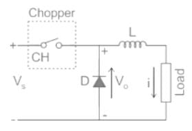
A DC chopper has a resistive load of R = 10 Ω and an input voltage of Vs = 220 V. When the chopper switch remains in the ON state, its voltage drop is Vch = 2 V. If the duty cycle is 50%, determine its average output voltage Vo.- a)111 V
- b)110 V
- c)109 V
- d)108 V
Correct answer is option 'C'. Can you explain this answer?
A DC chopper has a resistive load of R = 10 Ω and an input voltage of Vs = 220 V. When the chopper switch remains in the ON state, its voltage drop is Vch = 2 V. If the duty cycle is 50%, determine its average output voltage Vo.
a)
111 V
b)
110 V
c)
109 V
d)
108 V

|
Vertex Academy answered |
DC chopper
It is a power electronics device that is used to convert pure DC into pulsating DC.
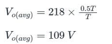
The average value of output voltage (pulsating value):
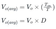
where, D is the duty cycle
Calculation
Source voltage (Vs) = 220 V
Vch = 2 V
When the chopper is in an ON state:
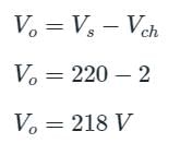
When the chopper is in an OFF state:
Vo = 0V
The waveform is given below:
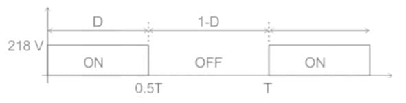
The average value of output voltage is:
In a type-A chopper, the maximum value of ripple current is- a)directly proportional to chopping frequency only.
- b)directly proportional to the circuit inductance only.
- c)directly proportional to chopping frequency and inversely proportional to the circuit inductance.
- d)inversely proportional to chopping frequency and the circuit inductance.
Correct answer is option 'D'. Can you explain this answer?
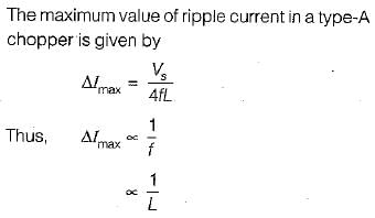
In a type-A chopper, the maximum value of ripple current is
a)
directly proportional to chopping frequency only.
b)
directly proportional to the circuit inductance only.
c)
directly proportional to chopping frequency and inversely proportional to the circuit inductance.
d)
inversely proportional to chopping frequency and the circuit inductance.
|
|
Aaditya Choudhary answered |
In the dc-dc converter circuit shown, switch Q is switched at a frequency of 10 kHz with a duty ratio of 0.6. All components of the circuit are ideal, and the initial current in the inductor is zero. Energy stored in the inductor in mJ (rounded off to 2 decimal places) at the end of 10 complete switching cycles is ________
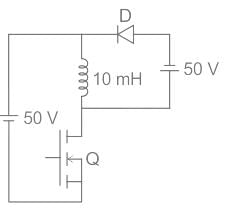
Correct answer is between '4.95,5.05'. Can you explain this answer?
In the dc-dc converter circuit shown, switch Q is switched at a frequency of 10 kHz with a duty ratio of 0.6. All components of the circuit are ideal, and the initial current in the inductor is zero. Energy stored in the inductor in mJ (rounded off to 2 decimal places) at the end of 10 complete switching cycles is ________
|
|
Cstoppers Instructors answered |
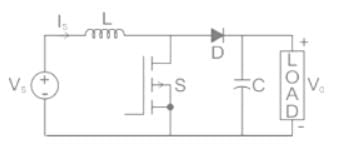
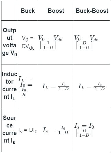
Identification of DC-DC Converter:
- Buck converter: Inductor is connected in series with the combination of the capacitor and load resistor.
- Boost converter: Inductor is connected in series with the supply voltage source.
- Buck-Boost converter: Inductor is connected in parallel to the series-connected switch and supply voltage source.
In a Buck-Boost converter, the inductor stores the energy for TON time and release the energy for the time TOFF
Given that, duty ratio (δ) = 0.6
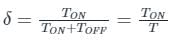
⇒ TON = δT = 0.6 T
⇒ TOFF = (1 – δ) T = 0.4 T
So, the inductor stores the energy for a time of 0.6 T and releases the energy for 0.4 T.
So, for one cycle, the increase in inductor current is corresponding to a time of (0.6 T – 0.4 T) = 0.2 T
Frequency (f) = 10 kHz
The time period for one cycle,
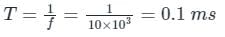
The waveform of the inductor current is as shown below.
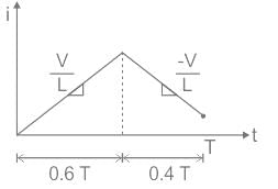
From the waveform, rise in the inductor current for one cycle

Rise in the inductor current for 10 cycles = 0.1 × 10 = 1 A
Energy stored in the inductor for 10 cycles,

Given that, duty ratio (δ) = 0.6
⇒ TON = δT = 0.6 T
⇒ TOFF = (1 – δ) T = 0.4 T
So, the inductor stores the energy for a time of 0.6 T and releases the energy for 0.4 T.
So, for one cycle, the increase in inductor current is corresponding to a time of (0.6 T – 0.4 T) = 0.2 T
Frequency (f) = 10 kHz
The time period for one cycle,
The waveform of the inductor current is as shown below.
From the waveform, rise in the inductor current for one cycle
Rise in the inductor current for 10 cycles = 0.1 × 10 = 1 A
Energy stored in the inductor for 10 cycles,
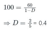
A step up chopper delivers an average output voltage of 100 V from an input supply of 60 V when operating with a continuous source current. What is the operating duty ratio for the switch?- a)1/3
- b)0.6
- c)0.4
- d)2/3
Correct answer is option 'C'. Can you explain this answer?
A step up chopper delivers an average output voltage of 100 V from an input supply of 60 V when operating with a continuous source current. What is the operating duty ratio for the switch?
a)
1/3
b)
0.6
c)
0.4
d)
2/3

|
Machine Experts answered |
Concept:
The circuit diagram of a boost converter is shown below.
A step-up or Boost converter is used to obtain the output voltage greater than the input voltage.
The relation between the output voltage and the input voltage is given by
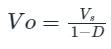
Where D is the duty cycle of the chopper
Calculation:
Input voltage (VS) = 100 V
Average output voltage (Vo) = 60 V
Consider the following statements:
1. DC chopper can be used in both dc and ac drives.
2. For four-quadrant operation dual converter is required.
3. Output voltage from a chopper circuit depends both on load current and duty cycle
4. In a step-down source, current can be discontinuous if duty cycle is low.
Which of the statements given above are correct?- a)1, 2 and 3
- b)2 and 4
- c)1, 3 and 4
- d)1 and 4
Correct answer is option 'B'. Can you explain this answer?
Consider the following statements:
1. DC chopper can be used in both dc and ac drives.
2. For four-quadrant operation dual converter is required.
3. Output voltage from a chopper circuit depends both on load current and duty cycle
4. In a step-down source, current can be discontinuous if duty cycle is low.
Which of the statements given above are correct?
a)
1, 2 and 3
b)
2 and 4
c)
1, 3 and 4
d)
1 and 4
|
|
Mainak Roy answered |
• DC choppers can be used in only dc drives.
• Output voltage from a chopper circuit depends only on duty cycle and is independent of load current.
Hence, statements 1 and 3 are not correct.
• Output voltage from a chopper circuit depends only on duty cycle and is independent of load current.
Hence, statements 1 and 3 are not correct.
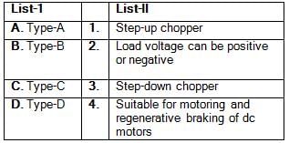
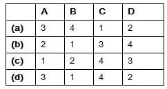
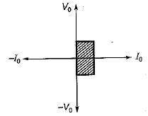
Match List-1 (Chopper circuit) with List-II (Characteristic) and select the correct answer using the codes given below the lists:
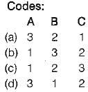
Codes:
- a)a
- b)b
- c)c
- d)d
Correct answer is option 'D'. Can you explain this answer?
Match List-1 (Chopper circuit) with List-II (Characteristic) and select the correct answer using the codes given below the lists:
Codes:
Codes:
a)
a
b)
b
c)
c
d)
d
|
|
Ishani Iyer answered |
• Type-A chopper is also called “step-down chopper” as average output voltage V0 is always less than the input dc voltage Vs.
• Type-B chopper is also called “step-up chopper” as load voltage
which is more than source voltage Vs.
• Type-C chopper configuration is suitable for motoring and degenerative braking of dc motors.
• Type-D chopper characteristic is shown below
• Type-B chopper is also called “step-up chopper” as load voltage
which is more than source voltage Vs.
• Type-C chopper configuration is suitable for motoring and degenerative braking of dc motors.
• Type-D chopper characteristic is shown below
Match List-I (Thyristor chopper circuits) wtih List-ll (Characteristics) and select the correct answer using the codes given below the lists:
List-I
A. Current commutated chopper
B. Voltage commutated chopper
C. Load commutated chopperList-ll
1. Diode in antiparallel with main SCR
2. Used in high power circuits
3. No requirement of any commutating inductor
- a)A
- b)B
- c)C
- d)D
Correct answer is option 'C'. Can you explain this answer?
Match List-I (Thyristor chopper circuits) wtih List-ll (Characteristics) and select the correct answer using the codes given below the lists:
List-I
A. Current commutated chopper
B. Voltage commutated chopper
C. Load commutated chopper
List-I
A. Current commutated chopper
B. Voltage commutated chopper
C. Load commutated chopper
List-ll
1. Diode in antiparallel with main SCR
2. Used in high power circuits
3. No requirement of any commutating inductor
1. Diode in antiparallel with main SCR
2. Used in high power circuits
3. No requirement of any commutating inductor
a)
A
b)
B
c)
C
d)
D
|
|
Vaibhav Mukherjee answered |
• In a current-commutated chopper a diode is connected in antiparallel with the main thyristor so that voltage drop across the diode reverse biases the main SCR.
• A voltage-commutated chopper is generally used in high-power circuits where load fluctuation is not very large.
• In a load-commutated chopper no commutating inductor is required that is normally costly, bulky and noisy.
• A voltage-commutated chopper is generally used in high-power circuits where load fluctuation is not very large.
• In a load-commutated chopper no commutating inductor is required that is normally costly, bulky and noisy.
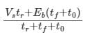
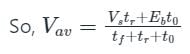
A step-down chopper operates from a DC voltage source Vs and feeds a DC motor armature with counter emf Eb. From oscilloscope traces it is found that current increases for time tr, falls to zero over a time tf and remains zero for a time t0 in every chopping cycle. Then the average voltage across the motor would be- a)

- b)

- c)

- d)
Correct answer is option 'C'. Can you explain this answer?
A step-down chopper operates from a DC voltage source Vs and feeds a DC motor armature with counter emf Eb. From oscilloscope traces it is found that current increases for time tr, falls to zero over a time tf and remains zero for a time t0 in every chopping cycle. Then the average voltage across the motor would be
a)
b)
c)
d)

|
Bayshore Academy answered |
During 0 < t < tr, the load is connected to the source and the voltage across the switch is Vs and load current increases.
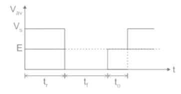
During tr < t < tf, the load current decreases. This implies that the back emf is connected to the load inductance and voltage across the switch is zero as the complete back emf is dropped overload inductance.
During tf < t < t0, the load current is zero, so back emf appears across the switch.
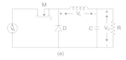
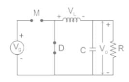
A buck converter, as shown in Figure (a) below, is working in steady state. The output voltage and the inductor current can be assumed to be ripple free. Figure (b) shows the inductor voltage VL during a complete switching interval. Assuming all devices are ideal, the duty cycle of the buck converter is ________.
 Correct answer is between '0.39,0.41'. Can you explain this answer?
A buck converter, as shown in Figure (a) below, is working in steady state. The output voltage and the inductor current can be assumed to be ripple free. Figure (b) shows the inductor voltage VL during a complete switching interval. Assuming all devices are ideal, the duty cycle of the buck converter is ________.
|
|
Vertex Academy answered |
Concept:
Buck converter: It is a switch mode DC to DC electronic converter in which the output voltage will be transformed to a level less than the input voltage. It is also called a step-down converter.
The output voltage of buck converter is given as:
Vo = D Vin
Where,
Vo is the output voltage
Vin is the input voltage
Iin is the input current
Io is the output current
D is the duty cycle
Calculation:
During ON time:
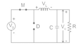
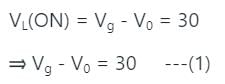
During OFF time:
In a 110 V de chopper drive using the CLC scheme, the maximum possible value of accelerating current is 200 A, the lower limit of the current pulsation is 140 A. The ON and OFF periods are 15 ms and 12 ms respectively. Calculate the chopping frequency.- a)1/27 Hz
- b)12 Hz
- c)15 Hz
- d)27 Hz
Correct answer is option 'D'. Can you explain this answer?
In a 110 V de chopper drive using the CLC scheme, the maximum possible value of accelerating current is 200 A, the lower limit of the current pulsation is 140 A. The ON and OFF periods are 15 ms and 12 ms respectively. Calculate the chopping frequency.
a)
1/27 Hz
b)
12 Hz
c)
15 Hz
d)
27 Hz
|
|
Sakshi Chauhan answered |
Understanding Chopping Frequency
To calculate the chopping frequency in a DC chopper drive system, we need to analyze the ON and OFF periods given.
Given Data:
- ON period (Ton) = 15 ms
- OFF period (Toff) = 12 ms
Calculating the Total Period:
The total period (T) of one complete cycle is the sum of the ON and OFF periods:
- T = Ton + Toff
- T = 15 ms + 12 ms
- T = 27 ms
Calculating the Chopping Frequency:
Chopping frequency (f) is the inverse of the total period:
- f = 1 / T
Substituting the value of T in seconds (1 ms = 0.001 s):
- T = 27 ms = 0.027 s
Now, calculating the frequency:
- f = 1 / 0.027 s ≈ 37.04 Hz
However, the frequency is usually expressed in terms of cycles per second, which is often approximated in practical applications.
Understanding the Options:
Upon reviewing the options provided:
- a) 1/27 Hz
- b) 12 Hz
- c) 15 Hz
- d) 27 Hz
The closest and most relevant answer derived from the calculated total period of 27 ms reflects the frequency effectively operating within the defined limits of the system.
Correct Answer:
Thus, the correct answer is option D: 27 Hz, which aligns with the calculations and system behavior.
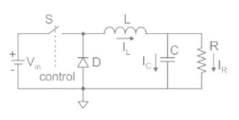
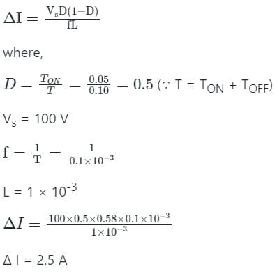
Figure (i) shows the circuit diagram of a chopper. The switch s in the circuit in the figure (i) is switched such that the voltage VD across the diode has the waveshape as shown in the figure (ii). The capacitance C is large so that the voltage across it is constant. If the switch s and diode d are idealThe peak to peak ripple (in A) in the inductor current is-
 Correct answer is between '2.40,2.60'. Can you explain this answer?
Figure (i) shows the circuit diagram of a chopper. The switch s in the circuit in the figure (i) is switched such that the voltage VD across the diode has the waveshape as shown in the figure (ii). The capacitance C is large so that the voltage across it is constant. If the switch s and diode d are ideal
The peak to peak ripple (in A) in the inductor current is-
|
|
Crack Gate answered |
Concept:
The circuit diagram of the buck converter is shown below.
The waveforms of current flows through the resistor, inductor, and capacitor are shown below.
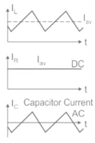
The waveforms of ripple current and voltage are shown below.
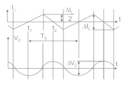
Calculation:
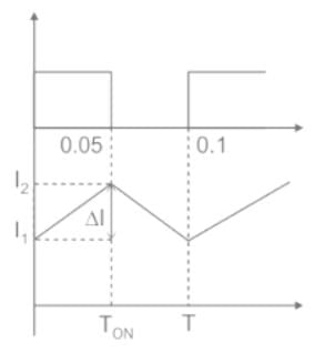
For buck converter, peak to peak ripple current is given by,
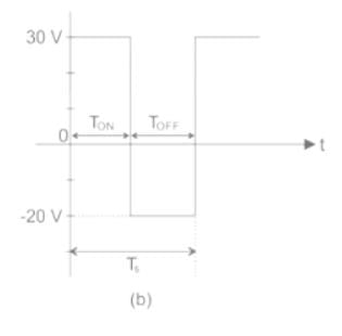
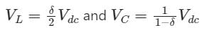
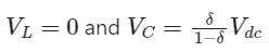
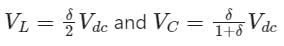
A self-commutating switch SW, operated at duty cycle δ is used to control the load voltage as shown in the figure.
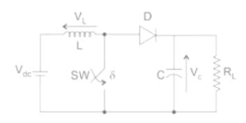
Under steady state operating conditions, the average voltage across the inductor and the capacitor respectively, are- a)
- b)
- c)
- d)
Correct answer is option 'A'. Can you explain this answer?
A self-commutating switch SW, operated at duty cycle δ is used to control the load voltage as shown in the figure.
Under steady state operating conditions, the average voltage across the inductor and the capacitor respectively, are
Under steady state operating conditions, the average voltage across the inductor and the capacitor respectively, are
a)
b)
c)
d)
|
|
Vibhor Goyal answered |
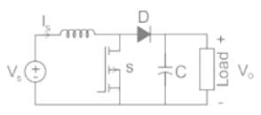
Identification of DC-DC Converter:
- Buck converter: Inductor is connected in series with the combination of the capacitor and resistor.
- Boost converter: Inductor is connected in series with the supply voltage source.
- Buck-Boost converter: Inductor is connected in parallel to the supply voltage source.
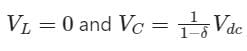
Under steady-state operating conditions:
- The average voltage across the inductor is zero. VL = 0
- The average current across the capacitor is zero. IC = 0
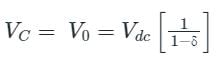
Given DC-DC converter is a Boost converter with duty cycle ratio δ.
The voltage across the load is the same as the voltage across the capacitor.
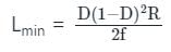
The minimum inductance (Lmin) for continuous current for a boost converter is given by (where D is duty ratio):- a)
- b)
- c)
- d)
Correct answer is option 'A'. Can you explain this answer?
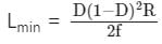
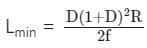
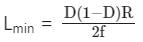
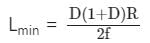
The minimum inductance (Lmin) for continuous current for a boost converter is given by (where D is duty ratio):
a)
b)
c)
d)
|
|
Vertex Academy answered |
Concept
At the edge of the continuous conduction, the value of inductance becomes minimum and such value of inductance is known as the critical inductance of the converter.
At the boundary of continuous conduction, IL(min) = 0
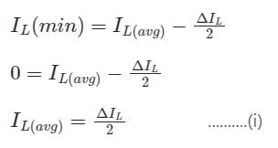
Calculation of ΔIL
When the switch is ON:

Putting this value in equation (i):
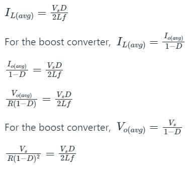
The value of the minimum inductance (Lmin) for continuous current for a boost converter is given by:
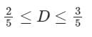
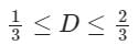
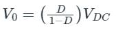
The input voltage VDC of the buck-boost converter shown below varies from 32 V to 72 V. Assume that all components are ideal, inductor current is continuous, and output voltage is ripple free. The range of duty ratio D of the converter for which the magnitude of the steady-state output voltage remains constant at 48 V is
- a)
- b)
- c)0 ≤ D ≤ 1
- d)
Correct answer is option 'A'. Can you explain this answer?
The input voltage VDC of the buck-boost converter shown below varies from 32 V to 72 V. Assume that all components are ideal, inductor current is continuous, and output voltage is ripple free. The range of duty ratio D of the converter for which the magnitude of the steady-state output voltage remains constant at 48 V is
a)
b)
c)
0 ≤ D ≤ 1
d)
|
|
Crack Gate answered |
Concept:
For a buck-boost converter,
Calculation:
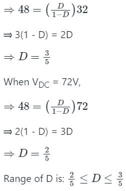
Given that,
Source voltage (VDC) = 32 V to 72 V
Output voltage, (V0) = 48 V
For a buck-boost converter,
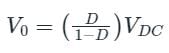
Where D is duty ratio
When VDC = 32V,
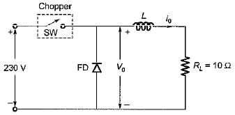
For the type-A chopper shown below, the voltage drop across the chopper when it is on is 2 volt. If the duty cycle is 0.4, then the chopper efficiency would be approximately equal to
- a)99%
- b)98%
- c)97%
- d)96%
Correct answer is option 'A'. Can you explain this answer?
For the type-A chopper shown below, the voltage drop across the chopper when it is on is 2 volt. If the duty cycle is 0.4, then the chopper efficiency would be approximately equal to
a)
99%
b)
98%
c)
97%
d)
96%
|
|
Prisha Iyer answered |
Given, Vs = 230 V
Load resistance, RL = 10Ω α = 0.4
When chopper is ON,
output voltage = (Vs - 2) volt
When chopper is OFF, output voltage = 0 volt
Average output voltage
Rms output voltage,
Power output delivered to load is
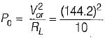
= 2079.364 Watt
Power input to chopper;
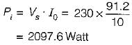
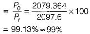
Chopper efficiency
Load resistance, RL = 10Ω α = 0.4
When chopper is ON,
output voltage = (Vs - 2) volt
When chopper is OFF, output voltage = 0 volt
Average output voltage
Rms output voltage,
Power output delivered to load is
= 2079.364 Watt
Power input to chopper;
Chopper efficiency
A step-down chopper has Vs as a source voltage, α is the duty ratio and R is the load resistance. The r.m.s. value of output voltage is- a)

- b)
- c)

- d)αVs
Correct answer is option 'C'. Can you explain this answer?
A step-down chopper has Vs as a source voltage, α is the duty ratio and R is the load resistance. The r.m.s. value of output voltage is
a)
b)
c)
d)
αVs
|
|
Bayshore Academy answered |
Step-down chopper:
Case 1: When the switch is ON
The diode is reverse biased.
VO = VS
Case 2: When the switch is OFF
The diode is reverse biased.
VO = 0
The r.m.s. value of output voltage is given by:
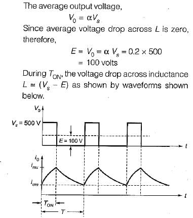
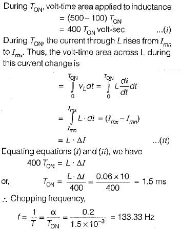
An RLE load is operating in a chopper circuit from a 500 volts dc source as shown in figure

For the load, L = 0.06H, R=0 Ω an duty cycle of 0.2, what is the chopping frequency to limit the amolitude of load current excursion to 10 A?- a)202.48 Hz
- b)98.60 Hz
- c)125.0 Hz
- d)133.33 Hz
Correct answer is option 'D'. Can you explain this answer?
An RLE load is operating in a chopper circuit from a 500 volts dc source as shown in figure
For the load, L = 0.06H, R=0 Ω an duty cycle of 0.2, what is the chopping frequency to limit the amolitude of load current excursion to 10 A?
For the load, L = 0.06H, R=0 Ω an duty cycle of 0.2, what is the chopping frequency to limit the amolitude of load current excursion to 10 A?
a)
202.48 Hz
b)
98.60 Hz
c)
125.0 Hz
d)
133.33 Hz
|
|
Anjali Choudhury answered |
Chapter doubts & questions for Choppers - Power Electronics 2025 is part of Electrical Engineering (EE) exam preparation. The chapters have been prepared according to the Electrical Engineering (EE) exam syllabus. The Chapter doubts & questions, notes, tests & MCQs are made for Electrical Engineering (EE) 2025 Exam. Find important definitions, questions, notes, meanings, examples, exercises, MCQs and online tests here.
Chapter doubts & questions of Choppers - Power Electronics in English & Hindi are available as part of Electrical Engineering (EE) exam.
Download more important topics, notes, lectures and mock test series for Electrical Engineering (EE) Exam by signing up for free.
Power Electronics
5 videos|67 docs|46 tests
|
|
© EduRev
|
Education Revolution
|


|


Signup on EduRev and stay on top of your study goals
10M+ students crushing their study goals daily