


All Exams >
Class 12 >
Physics Class 12 >
All Questions
All questions of CBSE Sample Question Papers for Class 12 Exam
An electron is accelerated through a potential difference of 7 volts. The energy gained by an electron will be- a)7 erg
- b)7 watt
- c)7 eV
- d)7 volt
Correct answer is option 'C'. Can you explain this answer?
An electron is accelerated through a potential difference of 7 volts. The energy gained by an electron will be
a)
7 erg
b)
7 watt
c)
7 eV
d)
7 volt
|
|
Mira Joshi answered |
Potential difference = 7 V
We know that
K.E. = 1/2mv2
here, 1/2mv2 = eV
K.E. = e x 7V
K.E. = 7eV
We know that
K.E. = 1/2mv2
here, 1/2mv2 = eV
K.E. = e x 7V
K.E. = 7eV

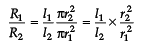
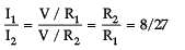
An electric current is passed through a circuit containing two wires of same material, connected in parallel. If the lengths and radii of the wires are in the ratio of 3 : 2 and 2 : 3, then the ratio of the current passing through the wire will be- a)2 : 3
- b)3 : 2
- c)8 : 27
- d)27 : 8
Correct answer is option 'C'. Can you explain this answer?
An electric current is passed through a circuit containing two wires of same material, connected in parallel. If the lengths and radii of the wires are in the ratio of 3 : 2 and 2 : 3, then the ratio of the current passing through the wire will be
a)
2 : 3
b)
3 : 2
c)
8 : 27
d)
27 : 8
|
|
Lavanya Menon answered |
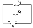
I1 : I2 = 3 : 2
r1 : r2 = 2 : 3
I1 : I2 = ?


=
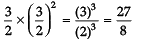
∴
Two bar magnets of the same mass, same length and same breadth have magnetic moments M and 3M, respectively, are joined together pole for pole and suspended by string. The time period of assembly is 3 seconds. Now, polarity of one magnet is reversed and combination is again forced to oscillate in magnetic field, the time of oscillation is- a)3
- b)2
- c)2√2
- d)3√2
Correct answer is option 'D'. Can you explain this answer?
Two bar magnets of the same mass, same length and same breadth have magnetic moments M and 3M, respectively, are joined together pole for pole and suspended by string. The time period of assembly is 3 seconds. Now, polarity of one magnet is reversed and combination is again forced to oscillate in magnetic field, the time of oscillation is
a)
3
b)
2
c)
2√2
d)
3√2
|
|
Riya Banerjee answered |
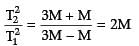
⇒ T2 = √2T1 = 3√2
The SI unit of magnetic field intensity is:- a)AmN–1
- b)NA–1m–1
- c)NA–2m–2
- d)NA–1m–2
Correct answer is option 'B'. Can you explain this answer?
The SI unit of magnetic field intensity is:
a)
AmN–1
b)
NA–1m–1
c)
NA–2m–2
d)
NA–1m–2
|
|
Kalyan Chavan answered |
SI Unit of Magnetic Field Intensity
Definition:
The SI unit of magnetic field intensity is Ampere per meter (A/m). It is denoted by the symbol NA–1m–1.
Explanation:
Ampere per meter (A/m) represents the magnetic field intensity produced by a current of one ampere flowing through a conductor per meter of length. It is a measure of the magnetic field strength at a specific point in space.
Relationship with Current:
The magnetic field intensity is directly proportional to the current flowing through the conductor. Therefore, increasing the current will result in a stronger magnetic field intensity.
Practical Applications:
The SI unit of magnetic field intensity is widely used in various applications, such as designing electromagnets, MRI machines, and magnetic sensors.
The amount of work done in bringing a charge of 10 mC from infinity to a point in an electric is 20 × 10–5 J. Electric potential at that point is- a)20 V
- b)200 V
- c)5V
- d)50V
Correct answer is option 'A'. Can you explain this answer?
The amount of work done in bringing a charge of 10 mC from infinity to a point in an electric is 20 × 10–5 J. Electric potential at that point is
a)
20 V
b)
200 V
c)
5V
d)
50V

|
Akshita Nair answered |
Explanation:
Given:
Charge q = 10 mC = 10 × 10^-3 C
Work done W = 20 × 10^-5 J
Electric Potential (V):
The electric potential at a point is defined as the work done in bringing a unit positive charge from infinity to that point. Mathematically, V = W/q
Calculation:
Given work done W = 20 × 10^-5 J and charge q = 10 × 10^-3 C
So, V = W/q = (20 × 10^-5) / (10 × 10^-3) = 2 V
Therefore, the electric potential at that point is 20 V.
So, the correct answer is option 'A'.
The magnetic flux linked with the coil (in Weber) is given by the equation:
φ = 5t2 + 3t + 16 The induced EMF in the coil at time, t = 4 will be:- a)- 27 V
- b)- 43 V
- c)- 108 V
- d)210 V
Correct answer is option 'B'. Can you explain this answer?
The magnetic flux linked with the coil (in Weber) is given by the equation:
φ = 5t2 + 3t + 16 The induced EMF in the coil at time, t = 4 will be:
φ = 5t2 + 3t + 16 The induced EMF in the coil at time, t = 4 will be:
a)
- 27 V
b)
- 43 V
c)
- 108 V
d)
210 V
|
|
Tanvi Bose answered |
The magnetic flux linked with the coil (in Weber) is given by the equation:
Φ = B * A * cos(θ)
Where:
- Φ is the magnetic flux linked with the coil, measured in Weber (Wb).
- B is the magnetic field strength, measured in Tesla (T).
- A is the cross-sectional area of the coil, measured in square meters (m^2).
- θ is the angle between the magnetic field lines and the normal to the coil's surface.
This equation represents the relationship between the magnetic field strength, the cross-sectional area of the coil, and the angle at which the magnetic field lines intersect the coil. The magnetic flux is a measure of the total magnetic field passing through the coil.
Two copper wires of same length, having different cross-sectional area in the ratio 1:3, are connected in series. The ratio of their drift velocities vd will be - a)3:1
- b)9:1
- c)1:3
- d)1:9
Correct answer is option 'A'. Can you explain this answer?
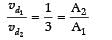
Two copper wires of same length, having different cross-sectional area in the ratio 1:3, are connected in series. The ratio of their drift velocities vd will be
a)
3:1
b)
9:1
c)
1:3
d)
1:9
|
|
Suresh Iyer answered |
Since, two copper wires are connected in series, current i flow through them is same. Both wires are made of same material, so n1 = n2
As, i = neAvd
⇒
⇒
⇒
As, i = neAvd
⇒
⇒
⇒
Electric potential at a point (x, y, z) in vacuum is V = 3x2 volt. Find the electric field intensity at the point (1m, 2m, 3m) . - a)1 V/m
- b)3 V/m
- c)6 V/m
- d)2 V/m
Correct answer is option 'C'. Can you explain this answer?
Electric potential at a point (x, y, z) in vacuum is V = 3x2 volt. Find the electric field intensity at the point (1m, 2m, 3m) .
a)
1 V/m
b)
3 V/m
c)
6 V/m
d)
2 V/m
|
|
Mihir Yadav answered |
Answer:
To find the electric field intensity at a given point, you need to differentiate the electric potential with respect to each coordinate and then take the negative gradient of the potential.
Given that the electric potential at a point (x, y, z) is V = 3x^2 volts, we can find the electric field intensity at the point (1m, 2m, 3m) by taking the negative gradient of the potential.
Calculating the electric field intensity:
To find the electric field intensity, we need to calculate the partial derivatives of the potential with respect to each coordinate.
- Partial derivative with respect to x: ∂V/∂x = 6x
- Partial derivative with respect to y: ∂V/∂y = 0 (since V does not depend on y)
- Partial derivative with respect to z: ∂V/∂z = 0 (since V does not depend on z)
Now, we can calculate the electric field intensity at the given point (1m, 2m, 3m) by substituting the coordinates into the partial derivatives:
- Electric field intensity in the x-direction: Ex = -∂V/∂x = -6(1) = -6 V/m
- Electric field intensity in the y-direction: Ey = -∂V/∂y = 0
- Electric field intensity in the z-direction: Ez = -∂V/∂z = 0
The electric field intensity at the point (1m, 2m, 3m) is given by the vector sum of the components:
E = sqrt(Ex^2 + Ey^2 + Ez^2)
= sqrt((-6 V/m)^2 + (0)^2 + (0)^2)
= sqrt(36 V^2/m^2)
= 6 V/m
Therefore, the correct answer is option 'C' - 6 V/m.
Assertion (A): Earth’s magnetic field does not affect the functioning of a moving coil galvanometer.
Reason (R): Earth’s magnetic field is too weak. - a)Both Assertion (A) and Reason (R) are true, and Reason(R) is the correct explanation of (A).
- b)Both Assertion (A) and Reason (R) are true, but Reason (R) is not the correct explanation of Assertion (A).
- c)Assertion (A) is true, but Reason (R) is false.
- d)Assertion (A) is false, but Reason (R) is true.
Correct answer is option 'A'. Can you explain this answer?
Assertion (A): Earth’s magnetic field does not affect the functioning of a moving coil galvanometer.
Reason (R): Earth’s magnetic field is too weak.
Reason (R): Earth’s magnetic field is too weak.
a)
Both Assertion (A) and Reason (R) are true, and Reason(R) is the correct explanation of (A).
b)
Both Assertion (A) and Reason (R) are true, but Reason (R) is not the correct explanation of Assertion (A).
c)
Assertion (A) is true, but Reason (R) is false.
d)
Assertion (A) is false, but Reason (R) is true.
|
|
Mira Joshi answered |
The coil of moving coil galvanometer is suspended in a very strong radial magnetic field. Earth’s magnetic field is too weak compared to that and hence its effect is negligible. So, assertion and reason both are true and the reason explains the assertion properly.
The magnetic field due to a current carrying circular loop of radius 3 cm at a point on the axis at a distance of 4 cm from the center is 54 mT. What will be its value at the centre of the loop?- a)300 μT
- b)500 μT
- c)250 μT
- d)150 μT
Correct answer is option 'C'. Can you explain this answer?
The magnetic field due to a current carrying circular loop of radius 3 cm at a point on the axis at a distance of 4 cm from the center is 54 mT. What will be its value at the centre of the loop?
a)
300 μT
b)
500 μT
c)
250 μT
d)
150 μT
|
|
Priyanka Sharma answered |
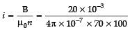
Magnetic field due to current carrying circular loop of radius a at a point on the axis at a distance x from the centre is given by
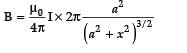
⇒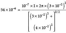
⇒ I = 11.94 A
Magnetic field at the centre =
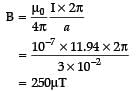
⇒
⇒ I = 11.94 A
Magnetic field at the centre =
By increasing the temperature, the specific resistance of a conductor and a semiconductor:- a)increases for both.
- b)decreases for both.
- c)increases for a conductor and decreases for a semiconductor.
- d)decreases for a conductor and increases for a semiconductor.
Correct answer is option 'C'. Can you explain this answer?
By increasing the temperature, the specific resistance of a conductor and a semiconductor:
a)
increases for both.
b)
decreases for both.
c)
increases for a conductor and decreases for a semiconductor.
d)
decreases for a conductor and increases for a semiconductor.

|
Saptarshi Ghoshal answered |
Introduction:
The specific resistance of a material is a measure of how strongly it opposes the flow of electric current. It is denoted by the symbol ρ (rho) and is dependent on factors such as temperature, material composition, and impurities. In this question, we are asked to determine the effect of temperature on the specific resistance of a conductor and a semiconductor.
Effect of Temperature on Specific Resistance:
Conductor:
In a conductor, the specific resistance generally increases with temperature. This can be explained by the increase in the lattice vibrations of the conductor's atoms as the temperature rises. These lattice vibrations cause more frequent collisions between the electrons and the atoms, resulting in increased resistance to the flow of current.
Semiconductor:
In a semiconductor, the effect of temperature on specific resistance is opposite to that of a conductor. The specific resistance of a semiconductor usually decreases with an increase in temperature. This phenomenon can be attributed to the increase in the number of charge carriers (electrons and holes) with rising temperature. As the temperature increases, more electrons are excited from the valence band to the conduction band, thereby increasing the conductivity and reducing the specific resistance of the semiconductor.
Conclusion:
In summary, the specific resistance of a conductor increases with temperature, while that of a semiconductor decreases. This behavior is consistent with the physics of these materials and can be explained by considering factors such as lattice vibrations and the generation of additional charge carriers.
The small angle between magnetic axis and geographic axis at a place is:- a)Magnetic meridian
- b)Geographic meridian
- c)Magnetic inclination
- d)Magnetic Declination
Correct answer is option 'D'. Can you explain this answer?
The small angle between magnetic axis and geographic axis at a place is:
a)
Magnetic meridian
b)
Geographic meridian
c)
Magnetic inclination
d)
Magnetic Declination
|
|
Suresh Iyer answered |
Correct option is Magnetic declination or Angle of declination. It is the small angle between geographic axis and magnetic axis.
Two coils of self-inductances 9 mH and 4 mH are placed so close together that the effective flux in one coil is linked with other. The mutual inductance between these coils is- a)6mH
- b)36mH
- c)4mH
- d)9mH
Correct answer is option 'A'. Can you explain this answer?
Two coils of self-inductances 9 mH and 4 mH are placed so close together that the effective flux in one coil is linked with other. The mutual inductance between these coils is
a)
6mH
b)
36mH
c)
4mH
d)
9mH

|
Milan Datta answered |
Mutual inductance is a measure of the extent to which the magnetic field generated by one coil links with the other coil. It is denoted by the symbol M. In this problem, we are given two coils with self-inductances of 9 mH and 4 mH respectively, and we need to find their mutual inductance.
The formula for mutual inductance is given by:
M = √(L1 * L2)
where L1 and L2 are the self-inductances of the two coils.
Given that L1 = 9 mH and L2 = 4 mH, we can substitute these values into the formula to find the mutual inductance:
M = √(9 * 4) = √36 = 6 mH
Therefore, the mutual inductance between the two coils is 6 mH.
To summarize:
- Given coils with self-inductances of 9 mH and 4 mH.
- Mutual inductance is a measure of the extent to which the magnetic field generated by one coil links with the other coil.
- The formula for mutual inductance is M = √(L1 * L2).
- Substituting the given values, we find that the mutual inductance is 6 mH.
Two point charges + 8q and –2q are located at x = 0 and x = L respectively. The point on x axis at which net electric field is zero due to these charges is- a)8L
- b)4L
- c)2L
- d)L
Correct answer is option 'C'. Can you explain this answer?
Two point charges + 8q and –2q are located at x = 0 and x = L respectively. The point on x axis at which net electric field is zero due to these charges is
a)
8L
b)
4L
c)
2L
d)
L
|
|
Nandini Iyer answered |
Let P be the observation point at a distance r from –2q and at (L + r) from + 8q.
Given Now, Net EFI at P = 0
 = EFI (Electric Field Intensity) at P due to + 8q
 = EFI (Electric Field Intensity) at P due to – 2q

∴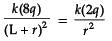
∴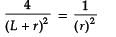
4r2 = (L + r)2
2r = L + r
r = L
∴ P is at x = L + L = 2L from origin
∴ Correct option is (C) 2L.
Given Now, Net EFI at P = 0
= EFI (Electric Field Intensity) at P due to + 8q = EFI (Electric Field Intensity) at P due to – 2q∴
∴
4r2 = (L + r)2
2r = L + r
r = L
∴ P is at x = L + L = 2L from origin
∴ Correct option is (C) 2L.
If the potential difference V applied across a conductor is increased to 2V with its temperature kept constant, the drift velocity of the free electrons in a conductor will:- a)remain the same.
- b)become half of its previous value.
- c)be double of its initial value.
- d)become zero.
Correct answer is option 'C'. Can you explain this answer?
If the potential difference V applied across a conductor is increased to 2V with its temperature kept constant, the drift velocity of the free electrons in a conductor will:
a)
remain the same.
b)
become half of its previous value.
c)
be double of its initial value.
d)
become zero.
|
|
Devanshi Mehta answered |
Introduction:
When a potential difference is applied across a conductor, it creates an electric field within the conductor which exerts a force on the free electrons present in the conductor. This force causes the electrons to drift in a particular direction, resulting in a net flow of charge or electric current.
Explanation:
To understand how the drift velocity of free electrons in a conductor changes when the potential difference is increased to 2V while keeping the temperature constant, let's consider the following points:
1. Relationship between drift velocity and applied potential difference:
The drift velocity of free electrons in a conductor is directly proportional to the applied potential difference. This means that as the potential difference increases, the drift velocity of the free electrons also increases.
2. Relationship between drift velocity and temperature:
The drift velocity of free electrons in a conductor is not directly affected by the temperature, as long as the temperature remains constant. Therefore, the drift velocity remains the same even when the temperature is constant.
3. Effect of increasing the potential difference:
When the potential difference across a conductor is increased to 2V, the electric field within the conductor becomes stronger. This stronger electric field exerts a greater force on the free electrons, causing them to accelerate and increase their drift velocity.
Conclusion:
Based on the above explanations, it can be concluded that when the potential difference applied across a conductor is increased to 2V while keeping the temperature constant, the drift velocity of the free electrons in the conductor will become double of its initial value. Therefore, the correct answer is option 'C'.
Assertion (A): If an electron is not deflected when moving through a certain region of space, then the only possibility is that no magnetic field is present in that region.
Reason (R): Force on electron is directly proportional to the strength of the magnetic field.- a)Both Assertion (A) and Reason (R) are true, and Reason(R) is the correct explanation of (A).
- b)Both Assertion (A) and Reason (R) are true, but Reason (R) is not the correct explanation of Assertion (A).
- c)Assertion (A) is true, but Reason (R) is false.
- d)Assertion (A) is false, but Reason (R) is true.
Correct answer is option 'A'. Can you explain this answer?
Assertion (A): If an electron is not deflected when moving through a certain region of space, then the only possibility is that no magnetic field is present in that region.
Reason (R): Force on electron is directly proportional to the strength of the magnetic field.
Reason (R): Force on electron is directly proportional to the strength of the magnetic field.
a)
Both Assertion (A) and Reason (R) are true, and Reason(R) is the correct explanation of (A).
b)
Both Assertion (A) and Reason (R) are true, but Reason (R) is not the correct explanation of Assertion (A).
c)
Assertion (A) is true, but Reason (R) is false.
d)
Assertion (A) is false, but Reason (R) is true.

|
Dipanjan Majumdar answered |
Assertion (A): If an electron is not deflected when moving through a certain region of space, then the only possibility is that no magnetic field is present in that region.
Reason (R): Force on electron is directly proportional to the strength of the magnetic field.
Correct answer: Option A - Both Assertion (A) and Reason (R) are true, and Reason (R) is the correct explanation of (A).
Explanation:
The given assertion and reason both deal with the behavior of an electron in the presence of a magnetic field. Let's analyze each statement separately:
Assertion (A): If an electron is not deflected when moving through a certain region of space, then the only possibility is that no magnetic field is present in that region.
When an electron moves through a magnetic field, it experiences a force called the magnetic force. This force acts perpendicular to both the velocity of the electron and the magnetic field. The magnitude of the force is given by the equation F = qvBsinθ, where q is the charge of the electron, v is its velocity, B is the strength of the magnetic field, and θ is the angle between the velocity and the magnetic field.
If an electron is not deflected when moving through a certain region of space, it means that the magnetic force acting on it is zero. This can only happen if there is no magnetic field present in that region. Therefore, Assertion (A) is true.
Reason (R): Force on electron is directly proportional to the strength of the magnetic field.
The reason states that the force on an electron is directly proportional to the strength of the magnetic field. This is in accordance with the equation mentioned earlier, F = qvBsinθ. As the strength of the magnetic field increases, the force on the electron also increases. Therefore, Reason (R) is true.
Explanation of Correct Answer:
Both Assertion (A) and Reason (R) are true, and Reason (R) correctly explains Assertion (A). When an electron is not deflected in a certain region, it indicates the absence of a magnetic field in that region. The reason for this is that the force on the electron is directly proportional to the strength of the magnetic field. If there is no magnetic field present, the force on the electron will be zero, resulting in no deflection.
Reason (R): Force on electron is directly proportional to the strength of the magnetic field.
Correct answer: Option A - Both Assertion (A) and Reason (R) are true, and Reason (R) is the correct explanation of (A).
Explanation:
The given assertion and reason both deal with the behavior of an electron in the presence of a magnetic field. Let's analyze each statement separately:
Assertion (A): If an electron is not deflected when moving through a certain region of space, then the only possibility is that no magnetic field is present in that region.
When an electron moves through a magnetic field, it experiences a force called the magnetic force. This force acts perpendicular to both the velocity of the electron and the magnetic field. The magnitude of the force is given by the equation F = qvBsinθ, where q is the charge of the electron, v is its velocity, B is the strength of the magnetic field, and θ is the angle between the velocity and the magnetic field.
If an electron is not deflected when moving through a certain region of space, it means that the magnetic force acting on it is zero. This can only happen if there is no magnetic field present in that region. Therefore, Assertion (A) is true.
Reason (R): Force on electron is directly proportional to the strength of the magnetic field.
The reason states that the force on an electron is directly proportional to the strength of the magnetic field. This is in accordance with the equation mentioned earlier, F = qvBsinθ. As the strength of the magnetic field increases, the force on the electron also increases. Therefore, Reason (R) is true.
Explanation of Correct Answer:
Both Assertion (A) and Reason (R) are true, and Reason (R) correctly explains Assertion (A). When an electron is not deflected in a certain region, it indicates the absence of a magnetic field in that region. The reason for this is that the force on the electron is directly proportional to the strength of the magnetic field. If there is no magnetic field present, the force on the electron will be zero, resulting in no deflection.
Two point charges placed in a medium of dielectric constant 5 are at a distance r between them, experience an electrostatic force ‘F’. The electrostatic force between them in vacuum at the same distance r will be:- a)5F
- b)F
- c)F/2
- d)F/5
Correct answer is option 'A'. Can you explain this answer?
Two point charges placed in a medium of dielectric constant 5 are at a distance r between them, experience an electrostatic force ‘F’. The electrostatic force between them in vacuum at the same distance r will be:
a)
5F
b)
F
c)
F/2
d)
F/5
|
|
Gaurav Kumar answered |
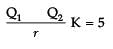
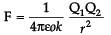
Q1 _______Q2
Force in the charges in the air is
= K F
= 5 F
The susceptibility of annealed iron at saturation is 5000. The permeability is - a)2.28 × 10⁻³
- b)6.28 × 10⁻³
- c)9.28 × 10⁻³
- d)1.28 × 10⁻³
Correct answer is option 'B'. Can you explain this answer?
The susceptibility of annealed iron at saturation is 5000. The permeability is
a)
2.28 × 10⁻³
b)
6.28 × 10⁻³
c)
9.28 × 10⁻³
d)
1.28 × 10⁻³
|
|
Mihir Yadav answered |
The permeability can be calculated using the formula:
Permeability = Susceptibility * (4π * 10^-7)
Given that the susceptibility of annealed iron at saturation is 5000, the permeability is:
Permeability = 5000 * (4π * 10^-7)
Permeability ≈ 2.257 x 10^-2
Therefore, the permeability of annealed iron at saturation is approximately 2.28.
Permeability = Susceptibility * (4π * 10^-7)
Given that the susceptibility of annealed iron at saturation is 5000, the permeability is:
Permeability = 5000 * (4π * 10^-7)
Permeability ≈ 2.257 x 10^-2
Therefore, the permeability of annealed iron at saturation is approximately 2.28.
Two coils are placed close to each other. The mutual inductance of the pair of coils depends upon the:- a)rate at which current change in the two coils
- b)relative position and orientation of the coils
- c)rate at which voltage induced across two coils
- d)currents in the two coils
Correct answer is option 'B'. Can you explain this answer?
Two coils are placed close to each other. The mutual inductance of the pair of coils depends upon the:
a)
rate at which current change in the two coils
b)
relative position and orientation of the coils
c)
rate at which voltage induced across two coils
d)
currents in the two coils
|
|
Shubham Jain answered |
Explanation:
When two coils are placed close to each other, the magnetic field produced by one coil will intersect the other coil. This will induce a voltage in the second coil. The mutual inductance of the pair of coils is a measure of the strength of this coupling. It is defined as the ratio of the induced voltage in one coil to the rate of change of current in the other coil.
Factors affecting mutual inductance:
Conclusion:
In conclusion, the mutual inductance of a pair of coils depends on several factors, including the relative position and orientation of the coils, the number of turns in each coil, the size of the coils, and the permeability of the medium between them.
When two coils are placed close to each other, the magnetic field produced by one coil will intersect the other coil. This will induce a voltage in the second coil. The mutual inductance of the pair of coils is a measure of the strength of this coupling. It is defined as the ratio of the induced voltage in one coil to the rate of change of current in the other coil.
Factors affecting mutual inductance:
- Relative position: The mutual inductance depends on the relative position and orientation of the two coils. If the coils are parallel and close to each other, the coupling will be stronger than if they are far apart or at an angle.
- Number of turns: The mutual inductance also depends on the number of turns in each coil. The more turns there are, the stronger the coupling will be.
- Size of coils: The size of the coils also affects the mutual inductance. Larger coils will have a stronger coupling than smaller coils.
- Permeability of the medium: The mutual inductance also depends on the permeability of the medium between the two coils. A higher permeability will result in a stronger coupling.
Conclusion:
In conclusion, the mutual inductance of a pair of coils depends on several factors, including the relative position and orientation of the coils, the number of turns in each coil, the size of the coils, and the permeability of the medium between them.
A charged particles enters into a magnetic field with an angle of 30° with respect to the direction of magnetic field. The path of the particle is- a)circular
- b)helical
- c)straight line
- d)elliptical
Correct answer is option 'B'. Can you explain this answer?
A charged particles enters into a magnetic field with an angle of 30° with respect to the direction of magnetic field. The path of the particle is
a)
circular
b)
helical
c)
straight line
d)
elliptical
|
|
Mira Joshi answered |
Charge is entered at point A making an angle 30°with the velocity v. one component of it is along the field and other component is perpendicular to it. Its perpendicular component v sin 30° will create circular motion, whereas its component along the field v cos 30° will have linear motion. Thus, resultant will have helical path.
Which of the following is NOT the property of equipotential surface?- a)They do not cross each other.
- b)The rate of change of potential with distance on them is zero.
- c)For a uniform electric field, they are concentric spheres.
- d)They can be imaginary spheres.
Correct answer is option 'C'. Can you explain this answer?
Which of the following is NOT the property of equipotential surface?
a)
They do not cross each other.
b)
The rate of change of potential with distance on them is zero.
c)
For a uniform electric field, they are concentric spheres.
d)
They can be imaginary spheres.
|
|
Nabanita Pillai answered |
Equipotential surface is a surface in an electric field on which all points have the same electric potential. Here, we need to identify the property that does not belong to equipotential surfaces.
Property not belonging to Equipotential Surface:
Concentric Spheres
Equipotential surfaces are defined as surfaces on which the electric potential is constant. Hence, the rate of change of potential with distance on them is zero. They do not cross each other and can be imaginary spheres. However, for a uniform electric field, equipotential surfaces are not concentric spheres. This is because the potential difference between two points in an electric field is directly proportional to the distance between them. Therefore, equipotential surfaces for a uniform electric field are plane surfaces perpendicular to the field lines.
In summary, the property that does not belong to equipotential surfaces is that for a uniform electric field, they are not concentric spheres.
Assertion (A): Potential difference between two points is depend on path.
Reason (R): Electric field is a conservative field.- a)Both Assertion (A) and Reason (R) are true, and Reason(R) is the correct explanation of (A).
- b)Both Assertion (A) and Reason (R) are true, but Reason (R) is not the correct explanation of Assertion (A).
- c)Assertion (A) is true, but Reason (R) is false.
- d)Assertion (A) is false, but Reason (R) is true.
Correct answer is option 'D'. Can you explain this answer?
Assertion (A): Potential difference between two points is depend on path.
Reason (R): Electric field is a conservative field.
Reason (R): Electric field is a conservative field.
a)
Both Assertion (A) and Reason (R) are true, and Reason(R) is the correct explanation of (A).
b)
Both Assertion (A) and Reason (R) are true, but Reason (R) is not the correct explanation of Assertion (A).
c)
Assertion (A) is true, but Reason (R) is false.
d)
Assertion (A) is false, but Reason (R) is true.
|
|
Riya Banerjee answered |
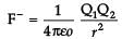
Potential difference between two points is defined as work done (W) in moving unit positive charge from one point A having potential VA to other point B having potential VB.
The work done is also explained as:

We know that F = qE
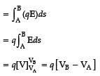
As, electric field at a point (x,y), i.e.

It concludes that whatever path S is selected on moving charge from A to B, the integral will have only one value. It means potential difference between two points is independent of path. So, assertion is not true. Electric field is a conservative field i.e. line integral of an electric field along a closed path is zero.
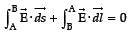
So, assertion is incorrect and reason is correct.
The work done is also explained as:
We know that F = qE
As, electric field at a point (x,y), i.e.
It concludes that whatever path S is selected on moving charge from A to B, the integral will have only one value. It means potential difference between two points is independent of path. So, assertion is not true. Electric field is a conservative field i.e. line integral of an electric field along a closed path is zero.
So, assertion is incorrect and reason is correct.
We use alloys for making standard resistors because they have:- a)low temperature coefficient of resistivity and high specific resistance.
- b)high temperature coefficient of resistivity and low specific resistance.
- c)low temperature coefficient of resistivity and low specific resistance.
- d)high temperature coefficient of resistivity and high specific resistance.
Correct answer is option 'A'. Can you explain this answer?
We use alloys for making standard resistors because they have:
a)
low temperature coefficient of resistivity and high specific resistance.
b)
high temperature coefficient of resistivity and low specific resistance.
c)
low temperature coefficient of resistivity and low specific resistance.
d)
high temperature coefficient of resistivity and high specific resistance.
|
|
Sreemoyee Sengupta answered |
Answer:
Introduction:
In the field of electronics, resistors are essential components used to control the flow of electric current. They are designed to have a specific resistance value, which determines the amount of current flowing through them. Resistors are made from various materials, including alloys, due to their advantageous properties.
Alloys for Making Standard Resistors:
The correct answer to why alloys are used for making standard resistors is option 'A' - low temperature coefficient of resistivity and high specific resistance. Let's understand why this is the case:
Low Temperature Coefficient of Resistivity:
The temperature coefficient of resistivity measures how much the resistance of a material changes with temperature. For standard resistors, it is desirable to have a low temperature coefficient of resistivity because it ensures that the resistance remains relatively constant over a wide range of temperatures.
When the temperature coefficient of resistivity is low, the change in resistance with temperature is minimal. This is important for accurately controlling the flow of current through a circuit, as resistors with stable resistance values provide consistent performance. Alloys, such as constantan and manganin, have low temperature coefficients of resistivity, making them ideal for standard resistors.
High Specific Resistance:
Specific resistance, also known as resistivity, is a measure of how strongly a material opposes the flow of electric current. For standard resistors, it is desirable to have a high specific resistance because it allows for the creation of resistors with higher resistance values.
By using alloys with high specific resistance, resistors with higher resistance values can be manufactured. This is essential in circuits where precise control of current flow is required. Alloys like nichrome and constantan have high specific resistance, making them suitable for standard resistors.
Conclusion:
In conclusion, alloys are used for making standard resistors because they possess a low temperature coefficient of resistivity and high specific resistance. These properties ensure that the resistance of the resistor remains stable over a wide range of temperatures and allows for the creation of resistors with higher resistance values. This is important for accurate and reliable control of current flow in electronic circuits.
The instantaneous values of emf and the current in a series ac circuit are: E = Eo sin ωt and I = Io sin (ωt + π/3) respectively, then it is- a)Necessarily a RL circuit
- b)Necessarily a RC circuit
- c)Necessarily a LCR circuit
- d)Can be RC or LCR circuit
Correct answer is option 'D'. Can you explain this answer?
The instantaneous values of emf and the current in a series ac circuit are: E = Eo sin ωt and I = Io sin (ωt + π/3) respectively, then it is
a)
Necessarily a RL circuit
b)
Necessarily a RC circuit
c)
Necessarily a LCR circuit
d)
Can be RC or LCR circuit

|
Arnab Chavan answered |
(ωt) and I = Io sin(ωt + φ), where Eo, Io, and φ are constants.
The emf E is given by Eo sin(ωt), where Eo represents the maximum value of the emf and ω is the angular frequency. The current I is given by Io sin(ωt + φ), where Io represents the maximum value of the current and φ is the phase angle.
In a series ac circuit, the emf and current are in phase with each other, meaning that the phase angle φ is 0. This means that the current reaches its maximum value Io at the same time as the emf reaches its maximum value Eo. Both the emf and current vary sinusoidally with time, following a sine function.
The angular frequency ω determines the rate at which the emf and current oscillate. It is related to the frequency f by the equation ω = 2πf, where f is the frequency of the alternating current.
Overall, the instantaneous values of the emf and current in a series ac circuit can be represented by the equations E = Eo sin(ωt) and I = Io sin(ωt), respectively.
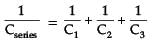
The equivalent resistance between A and B is ?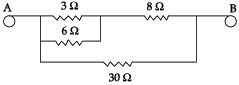
- a)3 ohms
- b)5.5 ohms
- c)7.5 ohms
- d)9.5 ohms
Correct answer is option 'C'. Can you explain this answer?
The equivalent resistance between A and B is ?
a)
3 ohms
b)
5.5 ohms
c)
7.5 ohms
d)
9.5 ohms
|
|
Riya Banerjee answered |
Redrawing the circuit, we get
3 Ω & 6 Ω are in parallel.
∴ R1 = 3 x 6 / 3 + 6 = 18/9 = 2
3 Ω & 6 Ω are in parallel.
∴ R1 = 3 x 6 / 3 + 6 = 18/9 = 2
Now R1 and 8Ω in series
∴ R2 = R1 + 8 = 2 + 8 = 10 Ω
Now R2 and 30Ωin parallel
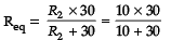
= 300/40 = 30/4 = 15 /2
= 7.5 Ω
∴ R2 = R1 + 8 = 2 + 8 = 10 Ω
Now R2 and 30Ωin parallel
= 300/40 = 30/4 = 15 /2
= 7.5 Ω


A capacitor plates are charged by a battery with ‘V’ volts. After charging, battery is disconnected and a dielectric slab with dielectric constant ‘K’ is inserted between its plates, the potential across the plates of a capacitor will become:- a)Zero
- b)V/2
- c)V/K
- d)KV
Correct answer is option 'C'. Can you explain this answer?
A capacitor plates are charged by a battery with ‘V’ volts. After charging, battery is disconnected and a dielectric slab with dielectric constant ‘K’ is inserted between its plates, the potential across the plates of a capacitor will become:
a)
Zero
b)
V/2
c)
V/K
d)
KV
|
|
Vivek Rana answered |
Battery is disconnected.
Q = Charge remains context C′ = KC
Q′ = C′V′
Q = C′V′
Q = KCV′
V′ = 
Which statement is true for Gauss law?- a)All the charges whether inside or outside the gaussian surface contribute to the electric flux.
- b)Electric flux depends upon the geometry of the gaussian surface.
- c)Gauss theorem can be applied to non-uniform electric field.
- d)The electric field over the gaussian surface remains continuous and uniform at every point.
Correct answer is option 'D'. Can you explain this answer?
Which statement is true for Gauss law?
a)
All the charges whether inside or outside the gaussian surface contribute to the electric flux.
b)
Electric flux depends upon the geometry of the gaussian surface.
c)
Gauss theorem can be applied to non-uniform electric field.
d)
The electric field over the gaussian surface remains continuous and uniform at every point.
|
|
Jyoti Sengupta answered |
All other statements except (iv) are incorrect.
The electric field over the Gaussian surface remains continuous and uniform at every point.
The electric field over the Gaussian surface remains continuous and uniform at every point.
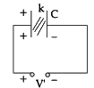
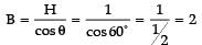
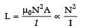
A constant voltage is applied between the two ends of a uniform metallic wire, heat ‘H’ is developed in it. If another wire of the same material, double the radius and twice the length as compared to original wire is used, then the heat developed in it will be:- a)H/2
- b)H
- c)2H
- d)4H
Correct answer is option 'C'. Can you explain this answer?
A constant voltage is applied between the two ends of a uniform metallic wire, heat ‘H’ is developed in it. If another wire of the same material, double the radius and twice the length as compared to original wire is used, then the heat developed in it will be:
a)
H/2
b)
H
c)
2H
d)
4H
|
|
Jyoti Sengupta answered |


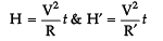
∵ V = constant
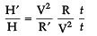
=
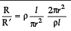
H′ /H = 2/1
H′ = 2H
Electrostatic force between two charged particles in air is F. If charges are placed at the same distance in brass, what will be the force?- a)zero
- b)F
- c)infinite
- d)None of these
Correct answer is option 'A'. Can you explain this answer?
Electrostatic force between two charged particles in air is F. If charges are placed at the same distance in brass, what will be the force?
a)
zero
b)
F
c)
infinite
d)
None of these
|
|
Advait Ghosh answered |
Explanation:
Electrostatic Force in Air:
When two charged particles are placed in air, the electrostatic force between them is denoted by F.
Electrostatic Force in Brass:
When the same charges are placed at the same distance in brass, the electrostatic force between them becomes zero.
Reason:
Brass is a conductor, which means it has free electrons that can move easily within the material. When charges are placed in brass, these free electrons rearrange themselves in such a way that the electric field inside the material becomes zero. Consequently, the electrostatic force between the charges in brass becomes zero.
Therefore, in the given scenario, the force between the charges in brass will be zero.
Two heaters A (500 W, 220 V) and B (1000 W, 220 V) are connected in parallel to 220 V. Which heater produces more heat- a)heater A
- b)heater B
- c)heater A and heater B produce same heat
- d)both heaters produce no heat
Correct answer is option 'B'. Can you explain this answer?
Two heaters A (500 W, 220 V) and B (1000 W, 220 V) are connected in parallel to 220 V. Which heater produces more heat
a)
heater A
b)
heater B
c)
heater A and heater B produce same heat
d)
both heaters produce no heat
|
|
Mihir Yadav answered |
Parallel Connection:
In a parallel connection, the devices are connected across the same voltage source. The voltage across each device is the same, but the current flowing through each device may vary.
Power Calculation:
The power consumed by an electrical device can be calculated using the formula:
Power = Voltage * Current
Heater A:
Power of heater A = 500 W
Voltage across heater A = 220 V
Using the power formula, we can calculate the current flowing through heater A:
Current = Power / Voltage = 500 W / 220 V = 2.27 A
Heater B:
Power of heater B = 1000 W
Voltage across heater B = 220 V
Using the power formula, we can calculate the current flowing through heater B:
Current = Power / Voltage = 1000 W / 220 V = 4.55 A
Comparison:
Since the voltage across both heaters is the same, the power produced by each heater is directly proportional to the current flowing through it.
In this case, the current flowing through heater B (4.55 A) is higher than the current flowing through heater A (2.27 A). Therefore, heater B produces more heat compared to heater A.
Conclusion:
The correct answer is option 'B' - heater B produces more heat.
A 20 volt AC is applied to a circuit consisting of a resistance and a coil with negligible resistance. If the voltage across the resistance is 12 volt, the voltage across the coil is:- a)16 V
- b)10 V
- c)8 V
- d)6 V
Correct answer is option 'A'. Can you explain this answer?
A 20 volt AC is applied to a circuit consisting of a resistance and a coil with negligible resistance. If the voltage across the resistance is 12 volt, the voltage across the coil is:
a)
16 V
b)
10 V
c)
8 V
d)
6 V
|
|
Suresh Iyer answered |
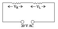
VR = Effective voltage across R
∴ VR = Ieff R
VL = Effective voltage across L
VL = Ieff × L
Net V =

=
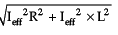
20 =

(20)2 = (12)2 + VL2
400 = 144 + VL2
VL = √400 - 144 = √266 = 16 volts
Assertion (A): A coulomb of charge is bigger than the charge on electron?
Reason (R): Electric charge is always quantized.- a)Both Assertion (A) and Reason (R) are true, and Reason(R) is the correct explanation of (A).
- b)Both Assertion (A) and Reason (R) are true, but Reason (R) is not the correct explanation of Assertion (A).
- c)Assertion (A) is true, but Reason (R) is false.
- d)Assertion (A) is false, but Reason (R) is true.
Correct answer is option 'A'. Can you explain this answer?
Assertion (A): A coulomb of charge is bigger than the charge on electron?
Reason (R): Electric charge is always quantized.
Reason (R): Electric charge is always quantized.
a)
Both Assertion (A) and Reason (R) are true, and Reason(R) is the correct explanation of (A).
b)
Both Assertion (A) and Reason (R) are true, but Reason (R) is not the correct explanation of Assertion (A).
c)
Assertion (A) is true, but Reason (R) is false.
d)
Assertion (A) is false, but Reason (R) is true.
|
|
Suresh Iyer answered |
Magnitude of charge on one electron, e = 1.6 × 10⁻¹⁹ Coulomb. According to the quantization of charge, charges of the particle (q) are integral multiple of charge of an electron/proton (e). i.e., q = ne. Therefore, number of charges in a coulomb,
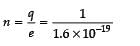
= 0.625 x10¹⁹
Clearly shows that one coulomb of charge is bigger than the charge on electron and quantization of charge is the correct reason for it. So, both assertion and reason are true.
= 0.625 x10¹⁹
Clearly shows that one coulomb of charge is bigger than the charge on electron and quantization of charge is the correct reason for it. So, both assertion and reason are true.
CASE STUDY
Read the following text and answer the questions
Electric potential at a point is defined as the amount of work done in bringing a unit positive charge from infinity to that point.
So, electric potential = work done divided by the amount of charge moved.
Negative charges move from lower to higher potential. Positive charges move from higher to lower potential.
Charges gain energy while moving through a potential difference. If an electron is accelerated from rest through a potential difference of 1V, it gains 1 eV energy.
Formula of electric potential- a) V = WQ
- b)V = W/Q
- c)W = VQ2
- d)V = WQ2
Correct answer is option 'B'. Can you explain this answer?
CASE STUDY
Read the following text and answer the questions
Electric potential at a point is defined as the amount of work done in bringing a unit positive charge from infinity to that point.
So, electric potential = work done divided by the amount of charge moved.
Negative charges move from lower to higher potential. Positive charges move from higher to lower potential.
Charges gain energy while moving through a potential difference. If an electron is accelerated from rest through a potential difference of 1V, it gains 1 eV energy.
Formula of electric potential
a)
V = WQ
b)
V = W/Q
c)
W = VQ2
d)
V = WQ2
|
|
Mira Joshi answered |
Electric potential at a point is defined using the following formula as V = W/Q, which states that the amount of work done in bringing a unit positive charge from infinity to that point is known as electric potential.
Two magnets are held together and are allowed to oscillate in the earth’s magnetic field with like poles together. 10 oscillations per minute are made but for unlike poles together only 4 oscillations per minutes are made. The ratio of magnetic moments is- a)16:21
- b)21:16
- c)29:21
- d)21:29
Correct answer is option 'C'. Can you explain this answer?
Two magnets are held together and are allowed to oscillate in the earth’s magnetic field with like poles together. 10 oscillations per minute are made but for unlike poles together only 4 oscillations per minutes are made. The ratio of magnetic moments is
a)
16:21
b)
21:16
c)
29:21
d)
21:29
|
|
Snehal Choudhary answered |
's magnetic field. The oscillation occurs because the magnetic field of the Earth exerts a force on the magnets, causing them to move back and forth.
When two magnets are held together, their magnetic fields interact with each other. If the magnets are aligned in the same direction, they will attract each other and stick together. However, if the magnets are aligned in opposite directions, they will repel each other and try to move apart.
In the Earth's magnetic field, the magnets experience a force due to the interaction between their magnetic fields and the Earth's magnetic field. This force causes the magnets to move, resulting in oscillation.
As the magnets move away from each other, the force of attraction between them decreases. Eventually, the force of repulsion between the magnets becomes stronger, causing them to move back towards each other. This back-and-forth motion continues, resulting in an oscillating motion.
The frequency and amplitude of the oscillation depend on factors such as the strength of the magnets, their distance apart, and the strength of the Earth's magnetic field. These factors determine the force exerted on the magnets and the rate at which they oscillate.
It's important to note that the Earth's magnetic field is relatively weak compared to the magnetic fields generated by permanent magnets. Therefore, the oscillation of the magnets in the Earth's magnetic field may not be very noticeable unless the magnets are relatively small or the Earth's magnetic field is amplified in some way.
Work done in moving an electron from one point to another on an equipotential surface of 10 Volt potential- a)10 eV
- b)10 V
- c)1eV
- d)zero
Correct answer is option 'D'. Can you explain this answer?
Work done in moving an electron from one point to another on an equipotential surface of 10 Volt potential
a)
10 eV
b)
10 V
c)
1eV
d)
zero
|
|
Tanuja Kapoor answered |
The potential difference between two points of equipotential surface i.e.
V2 - V1 = 0 = W/q ⇒ W = 0
Therefore, no work done is done in moving a charge from one point to another on an equipotential surface.
V2 - V1 = 0 = W/q ⇒ W = 0
Therefore, no work done is done in moving a charge from one point to another on an equipotential surface.
An electric dipole of moment p is placed parallel to the uniform electric field. The amount of work done in rotating the dipole by 90° is- a)2pE
- b)pE
- c)pE/2
- d)Zero
Correct answer is option 'B'. Can you explain this answer?
An electric dipole of moment p is placed parallel to the uniform electric field. The amount of work done in rotating the dipole by 90° is
a)
2pE
b)
pE
c)
pE/2
d)
Zero
|
|
Priyanka Sharma answered |
W = pE (cos θ1 – cos θ2)
θ1 = 0°
θ2 = 90°
W = pE (cos 0° – cos 90°)
= pE (1 – 0)
= PE
θ1 = 0°
θ2 = 90°
W = pE (cos 0° – cos 90°)
= pE (1 – 0)
= PE
When two bulbs A (40 W, 220 V) and B (60 W, 220 V) are connected in series, which bulb is brighter. - a)bulb A
- b)bulb B
- c)both
- d)none of these
Correct answer is option 'A'. Can you explain this answer?
When two bulbs A (40 W, 220 V) and B (60 W, 220 V) are connected in series, which bulb is brighter.
a)
bulb A
b)
bulb B
c)
both
d)
none of these
|
|
Shalini Patel answered |
As
P = V x i = i2R = V2/R
R for 40 W bulb
R40 = V2/P = (200)2/40 = 1210Ω
R for 60 W bulb
R60 = V2/P = (200)2/60 = 806.67Ω
⇒ R40>R60
When two bulbs are connected in series, current flow through them is same and power is calculated using the following formula:
P = i2R or P ∞ R
Since, R40 > R60 therefore, P40 > P60 Therefore, power dissipation is large in 40 W bulb as compare to 60 W bulb. 40 W bulb is brighter than 60 W.
Assertion (A): Potentiometer measures the potential difference more accurately than a voltmeter.
Reason (R): There is no current drawn from external circuit in potentiometer.- a)Both Assertion (A) and Reason (R) are true, and Reason(R) is the correct explanation of (A).
- b)Both Assertion (A) and Reason (R) are true, but Reason (R) is not the correct explanation of Assertion (A).
- c)Assertion (A) is true, but Reason (R) is false.
- d)Assertion (A) is false, but Reason (R) is true.
Correct answer is option 'A'. Can you explain this answer?
Assertion (A): Potentiometer measures the potential difference more accurately than a voltmeter.
Reason (R): There is no current drawn from external circuit in potentiometer.
Reason (R): There is no current drawn from external circuit in potentiometer.
a)
Both Assertion (A) and Reason (R) are true, and Reason(R) is the correct explanation of (A).
b)
Both Assertion (A) and Reason (R) are true, but Reason (R) is not the correct explanation of Assertion (A).
c)
Assertion (A) is true, but Reason (R) is false.
d)
Assertion (A) is false, but Reason (R) is true.
|
|
Priyanka Sharma answered |
When a potential difference is measured using a voltmeter, voltmeter draws some current and when it is connected across the cell, there is a internal potential drop due to the internal resistance of the cell. Hence, measuring potential will not be accurate. In potentiometer, there is no current drawn from external circuit.
Therefore, both assertion and reason are correct and reason is also the correct explanation of A.
Therefore, both assertion and reason are correct and reason is also the correct explanation of A.
A bar magnet having magnetic moment 0.4 JT–1 is placed in a uniform magnetic field of 0.16 T. The magnet is in stable equilibrium when the potential energy is- a)zero
- b)–0.64 J
- c)–0.064 J
- d)–6.40 J
Correct answer is option 'C'. Can you explain this answer?
A bar magnet having magnetic moment 0.4 JT–1 is placed in a uniform magnetic field of 0.16 T. The magnet is in stable equilibrium when the potential energy is
a)
zero
b)
–0.64 J
c)
–0.064 J
d)
–6.40 J
|
|
Riya Banerjee answered |
In stable equilibrium, Potential energy U is defined as
U = 0MB
= - (0.4)(0.16)
= - 0.064J
U = 0MB
= - (0.4)(0.16)
= - 0.064J
When A wire of resistance 12 R is bent to form a circle. The effective resistance across its diameter is- a)2R
- b)3R
- c)4R
- d)R
Correct answer is option 'B'. Can you explain this answer?
When A wire of resistance 12 R is bent to form a circle. The effective resistance across its diameter is
a)
2R
b)
3R
c)
4R
d)
R
|
|
Rajesh Gupta answered |
Given that resistance of wire 12 Ω. It is bent and form circle, then resistance f each semicircle is 6 Ω. Now, measuring the resistance across its diameter, these two resistances are in parallel. Their effective resistance

=3R
=3R
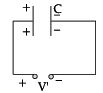
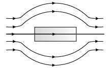
The given figure represents the material which is
- a)ferrimagnetic
- b)ferromagnetic
- c)diamagnetic
- d)paramagnetic
Correct answer is option 'C'. Can you explain this answer?
The given figure represents the material which is
a)
ferrimagnetic
b)
ferromagnetic
c)
diamagnetic
d)
paramagnetic
|
|
Mira Joshi answered |
The given figure represents that magnetic field lines move away from the substance. The diamagnetic material has susceptibility c = 0, causing the repelling of magnetic field lines, Hence, given material is diamagnetic material
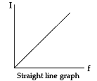
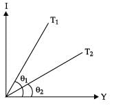
In the V-I graph for a given metallic wire at two different temperatures T1 and T2 are shown in figure. The relationship between T1 and T2 is
- a)T1 = T2
- b)T1 ∠ T2
- c)T1 > T2
- d)none of these
Correct answer is option 'C'. Can you explain this answer?
In the V-I graph for a given metallic wire at two different temperatures T1 and T2 are shown in figure. The relationship between T1 and T2 is
a)
T1 = T2
b)
T1 ∠ T2
c)
T1 > T2
d)
none of these
|
|
Mira Joshi answered |
Given figure shows that slope of the line corresponding to T1 is greater than the slope of the line at T2, i.e., tan θ1 > tan θ2, which indicates that T1 > T2.
A current i ampere flows along an infinite long straight tube, then the magnetic induction at any point inside - a)zero
- b)infinite
- c)

- d)

Correct answer is option 'A'. Can you explain this answer?
A current i ampere flows along an infinite long straight tube, then the magnetic induction at any point inside
a)
zero
b)
infinite
c)
d)
|
|
Riya Banerjee answered |
Using Ampere’s law

Here, i is zero, for r < R, where R is radius of the tube
∴ B = 0
Here, i is zero, for r < R, where R is radius of the tube
∴ B = 0
The coil of a moving coil galvanometer is wound over a metal frame in order to:- a)reduce hysteresis
- b)increase sensitivity
- c)increase moment of inertia
- d)provide electromagnetic damping
Correct answer is option 'D'. Can you explain this answer?
The coil of a moving coil galvanometer is wound over a metal frame in order to:
a)
reduce hysteresis
b)
increase sensitivity
c)
increase moment of inertia
d)
provide electromagnetic damping
|
|
Priyanka Sharma answered |
The coil of a moving coil galvanometer is wound over metallic frame to provide electromagnetic damping so it becomes dead beat galvanometer.
Chapter doubts & questions for CBSE Sample Question Papers - Physics Class 12 2025 is part of Class 12 exam preparation. The chapters have been prepared according to the Class 12 exam syllabus. The Chapter doubts & questions, notes, tests & MCQs are made for Class 12 2025 Exam. Find important definitions, questions, notes, meanings, examples, exercises, MCQs and online tests here.
Chapter doubts & questions of CBSE Sample Question Papers - Physics Class 12 in English & Hindi are available as part of Class 12 exam.
Download more important topics, notes, lectures and mock test series for Class 12 Exam by signing up for free.
Physics Class 12
127 videos|452 docs|99 tests
|
|
© EduRev
|
Education Revolution
|


|


Signup to see your scores
go up within 7 days!
Access 1000+ FREE Docs, Videos and Tests
Takes less than 10 seconds to signup