


All Exams >
Class 12 >
Physics Class 12 >
All Questions
All questions of Alternating Current for Class 12 Exam
Alternating current is represented by- a)
- b)

- c)

- d)

Correct answer is option 'A'. Can you explain this answer?
Alternating current is represented by
a)
b)
c)
d)

|
Divey Sethi answered |
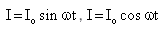
Alternating current is an electric current which periodically reverses direction, as opposed to direct current which flows only in one direction. And it can be easily represented by the periodic function.
So, I = Io sin wt or I = lo cos wt.
So, I = Io sin wt or I = lo cos wt.

The average power dissipation in pure resistive circuit is:- a)

- b)

- c)

- d)

Correct answer is option 'D'. Can you explain this answer?
The average power dissipation in pure resistive circuit is:
a)
b)
c)
d)
|
|
Divey Sethi answered |
Power=IV
Where I=Vrms value of current=IV
And V=Vrms value of voltage=EV
Therefore, P=EVIV
Where I=Vrms value of current=IV
And V=Vrms value of voltage=EV
Therefore, P=EVIV
Find the instantaneous voltage for an a.c. supply of 200V and 75 hertz- a)E = 282.8 sin 50πt
- b)E = 282.8 sin 150πt
- c)E = 282.8 sin 75πt
- d)E = 282.8 sin 100πt
Correct answer is option 'B'. Can you explain this answer?
Find the instantaneous voltage for an a.c. supply of 200V and 75 hertz
a)
E = 282.8 sin 50πt
b)
E = 282.8 sin 150πt
c)
E = 282.8 sin 75πt
d)
E = 282.8 sin 100πt
|
|
Krishna Iyer answered |
Answer :- b
Solution :- f = 75hz
w=2πf
= 2 * π * 75
= 150π
E(max) = (2)^½ E(rms)
E(max) = 1.414 * 200
= 282.8V
E(ins) = E(max)sinwt
E(ins) = 282.8 sin 150πt
Which is more dangerous?- a)220 V a.c
- b)220 V d.c
- c)Both 220 V a.c. and 220 V d.c
- d)Both 220 V a.c. and 220 V d.c. are not dangerous
Correct answer is option 'A'. Can you explain this answer?
Which is more dangerous?
a)
220 V a.c
b)
220 V d.c
c)
Both 220 V a.c. and 220 V d.c
d)
Both 220 V a.c. and 220 V d.c. are not dangerous
|
|
Mihir Joshi answered |
The correct answer is option 'A', i.e., 220 V a.c.
Explanation:
Electricity can be transmitted in two forms - AC (alternating current) and DC (direct current). Both forms of electricity can be dangerous but the level of danger depends on various factors such as voltage, current, resistance, frequency, and duration of exposure.
Let's understand why 220 V a.c. is more dangerous than 220 V d.c.:
1. Effect on the human body:
- AC current alternates its direction of flow and causes muscle contractions and spasms, making it difficult for a person to let go of the source of electricity. This increases the risk of electrocution and can be fatal.
- DC current flows in one direction and causes muscle contractions and spasms but it is easier to let go of the source of electricity.
2. Frequency:
- AC current has a frequency of 50 or 60 Hz, which means it alternates its direction 50 or 60 times per second. This rapid change in direction makes it more dangerous and can affect the heart rhythm.
- DC current has a frequency of 0 Hz, which means it flows in one direction only and does not affect the heart rhythm.
3. Appliances and devices:
- Most household appliances and devices run on AC current, which means the chances of coming into contact with AC electricity are higher.
- DC current is mainly used in batteries, electronic devices, and some industrial applications.
Therefore, based on the above factors, it can be concluded that 220 V a.c. is more dangerous than 220 V d.c. However, it is important to note that both forms of electricity can be lethal and should be handled with caution. It is recommended to always turn off the power source before working on electrical equipment and to wear protective gear.
In an inductance the current- a)is in phase
- b)leads the voltage
- c)lags the voltage
- d)builds very fast
Correct answer is option 'C'. Can you explain this answer?
In an inductance the current
a)
is in phase
b)
leads the voltage
c)
lags the voltage
d)
builds very fast
|
|
Krishna Iyer answered |
In an inductor, current lags behind the input voltage by a phase difference of π/2.
Current and voltage are in the same phase in the resistor whereas current leads the voltage by π/2 in a capacitor.
So, the circuit must contain an inductor only.
Current and voltage are in the same phase in the resistor whereas current leads the voltage by π/2 in a capacitor.
So, the circuit must contain an inductor only.
The only component that dissipates energy in ac circuit is:- a)Capacitor
- b)Inductor
- c)Resistors
- d)None of these
Correct answer is option 'C'. Can you explain this answer?
The only component that dissipates energy in ac circuit is:
a)
Capacitor
b)
Inductor
c)
Resistors
d)
None of these
|
|
Hansa Sharma answered |
The only component that dissipates energy in ac circuit is the resistor because Pure Inductive and pure capacitive circuits have no power loss.
What is the relationship between Em and E0- a)Em=-0.537 E0
- b)Em=-0.737 E0
- c)Em=-0.637 E0
- d)Em=-0.707 E0
Correct answer is option 'C'. Can you explain this answer?
What is the relationship between Em and E0
a)
Em=-0.537 E0
b)
Em=-0.737 E0
c)
Em=-0.637 E0
d)
Em=-0.707 E0
|
|
Om Desai answered |
peak value Em=2E0/π
so 2/π value is 0.637
therefore,
Em=-0.637 E0
so 2/π value is 0.637
therefore,
Em=-0.637 E0
Admittance is reciprocal of- a)Susceptance
- b)Reactance
- c)Impedance
- d)Capacitance
Correct answer is option 'C'. Can you explain this answer?
Admittance is reciprocal of
a)
Susceptance
b)
Reactance
c)
Impedance
d)
Capacitance

|
Aashika Packiaselvam. answered |
Look.. Impendenc means a kind of opposition to a steady electric current ie. resistance. While admittance is a measure to how easily a circuit or device will allow a current to flow. Here by looking at the definition itself, we can clearly say that they are inverse of each other.
What is value of power factor if Ø = 90°- a)0
- b)0.5
- c)1
- d)infinite
Correct answer is option 'A'. Can you explain this answer?
What is value of power factor if Ø = 90°
a)
0
b)
0.5
c)
1
d)
infinite

|
Sidharth Gupta answered |
Power factor = cos(angle ) that is in this case 90 so cos90 is zero
Power in an ac circuit is equal to- a)Instantaneous voltage X Instantaneous current
- b)Instantaneous voltage X current at an instant
- c)Voltage at an instant X Instantaneous current
- d)Both b and c
Correct answer is option 'A'. Can you explain this answer?
Power in an ac circuit is equal to
a)
Instantaneous voltage X Instantaneous current
b)
Instantaneous voltage X current at an instant
c)
Voltage at an instant X Instantaneous current
d)
Both b and c

|
Imk Pathsala answered |
Explanation:
Power in an AC circuit is equal to Instantaneous voltage X Instantaneous current:
- In an AC circuit, both voltage and current vary with time, and power is the rate at which work is done or energy is transferred.
- Power in an AC circuit is given by the product of the instantaneous voltage and the instantaneous current at any given moment.
- This means that at any instant, the power being dissipated or consumed in the circuit can be calculated by multiplying the instantaneous voltage and current values at that particular moment.
- Mathematically, the formula for power in an AC circuit is P = V(t) * I(t), where P is power, V(t) is the instantaneous voltage, and I(t) is the instantaneous current at a given time t.
- Therefore, the correct answer is A: Instantaneous voltage X Instantaneous current.
Given the instantaneous value of current from a.c. source is I = 8 sin 623t. Find the r.m.s value of current- a)5.656 A
- b)8 A
- c)2.848 A
- d)1.414 A
Correct answer is option 'A'. Can you explain this answer?
Given the instantaneous value of current from a.c. source is I = 8 sin 623t. Find the r.m.s value of current
a)
5.656 A
b)
8 A
c)
2.848 A
d)
1.414 A
|
|
Om Desai answered |
Compare the given eqn. with the standard from I=I0sinωt
I0=8, Irms=I0/√2=8/√2=5.656A
I0=8, Irms=I0/√2=8/√2=5.656A
In a series LCR what will be phase difference between voltage drop across inductor and capacitor- a)0
- b)90
- c)180
- d)45
Correct answer is option 'C'. Can you explain this answer?
In a series LCR what will be phase difference between voltage drop across inductor and capacitor
a)
0
b)
90
c)
180
d)
45

|
Rajendri Rani answered |
Because In C-R circuit current lead by π/2 and in L-R circuit voltage lead by π/2 so after drawing the phasor diagram and current will be same so the phase difference is 2π
If a capacitor of capacitance 9.2F has a voltage of 22.5V across it. Calculate the energy of the capacitor.- a)5062.5 J
- b) 2328.75 J
- c)50.625 J
- d)50625 J
Correct answer is option 'B'. Can you explain this answer?
If a capacitor of capacitance 9.2F has a voltage of 22.5V across it. Calculate the energy of the capacitor.
a)
5062.5 J
b)
2328.75 J
c)
50.625 J
d)
50625 J
|
|
Geetika Shah answered |
We know that,
ω=(1/2)CV2
After putting the values,
=(1/2)x9.2x22.5x22.5
=2328.75J
Hence option B is the answer.
ω=(1/2)CV2
After putting the values,
=(1/2)x9.2x22.5x22.5
=2328.75J
Hence option B is the answer.
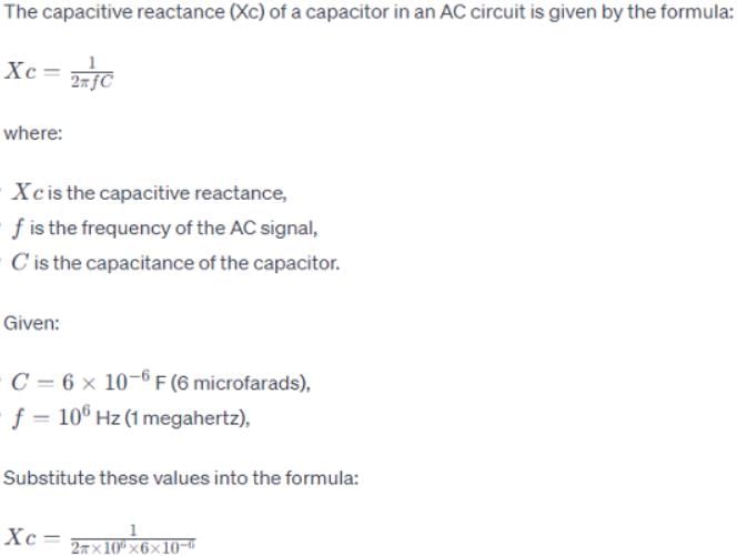
What is the unit of Capacitive Reactance Xc?- a)Ohm
- b)Ohm2
- c)Ohm-1
- d)mhO
Correct answer is option 'A'. Can you explain this answer?
What is the unit of Capacitive Reactance Xc?
a)
Ohm
b)
Ohm2
c)
Ohm-1
d)
mhO
|
|
Krishna Iyer answered |
The opposition offered by a capacitor for the flow of A.C is called capacitive reactance.
Xc = 1/wC
it's SI unit is ohm
Xc = 1/wC
it's SI unit is ohm
The current amplitude in a pure inductor in a radio receiver is to be 250 μA when the voltage amplitude is 3.60 V at a frequency of 1.60 MHz (at the upper end of the AM broadcast band). If the voltage amplitude is kept constant, what will be the current amplitude through this inductor at 16.0 MHz?- a)20.0 μA
- b)33.0 μA
- c).35.0 μA
- d)25.0 μA
Correct answer is option 'D'. Can you explain this answer?
The current amplitude in a pure inductor in a radio receiver is to be 250 μA when the voltage amplitude is 3.60 V at a frequency of 1.60 MHz (at the upper end of the AM broadcast band). If the voltage amplitude is kept constant, what will be the current amplitude through this inductor at 16.0 MHz?
a)
20.0 μA
b)
33.0 μA
c)
.35.0 μA
d)
25.0 μA
|
|
Preeti Khanna answered |
I0=250μA, v0=3.6v . v=1.6x10⁶ Hz
Here,
(Reactance of inductance) XL=ωL
XL=2πv X L
v0/I0=2πv x L
3.6/2.5x10-4=2πx1.6x10-6 x L
0.14x10⁴-6=L
L=0.14x10⁻²H
Now for v=16.0x10⁶Hz
XL=2πv X L
=2πx16x106x14x10-4
XL=1407x102Ω
Now,
v0=I0 x XL
3.6/1407x102=I0 [∵v0=kept constant.]
I0=0.00256x10⁻²
I0=25.6μA
Here,
(Reactance of inductance) XL=ωL
XL=2πv X L
v0/I0=2πv x L
3.6/2.5x10-4=2πx1.6x10-6 x L
0.14x10⁴-6=L
L=0.14x10⁻²H
Now for v=16.0x10⁶Hz
XL=2πv X L
=2πx16x106x14x10-4
XL=1407x102Ω
Now,
v0=I0 x XL
3.6/1407x102=I0 [∵v0=kept constant.]
I0=0.00256x10⁻²
I0=25.6μA
Find the series resonance frequency when L = 0.09 H, C = 25 F- a)10.6 s-1
- b)0.106 s-1
- c)1.66 s-1
- d)1.06 s-1
Correct answer is option 'B'. Can you explain this answer?
Find the series resonance frequency when L = 0.09 H, C = 25 F
a)
10.6 s-1
b)
0.106 s-1
c)
1.66 s-1
d)
1.06 s-1
|
|
Lavanya Menon answered |
ω=1/√LC
ω=1√0.09x25
ω=0.666
ω=2πf
f=0.666/(2 x 3.14)
f=0.106 s-1
ω=1√0.09x25
ω=0.666
ω=2πf
f=0.666/(2 x 3.14)
f=0.106 s-1
Virtual value or effective value of a.c. is- a)-0.637I0
- b)-0.707I0
- c)0.637I0
- d)0.707I0
Correct answer is option 'D'. Can you explain this answer?
Virtual value or effective value of a.c. is
a)
-0.637I0
b)
-0.707I0
c)
0.637I0
d)
0.707I0
|
|
Preeti Iyer answered |
R.M.S. value or effective value or virtual value of Alternating current is given by
Irms = eo/√2 = 𝐼𝑝𝑒𝑎𝑘/√2 = 0.707 Io.
Irms = eo/√2 = 𝐼𝑝𝑒𝑎𝑘/√2 = 0.707 Io.
A hair dryer meant for 110V 60Hz is to be used in India . If 220 V is the supply voltage in India , the turns ratio for a transformer would be- a)step-down 2.5:1
- b)step-up 1:2
- c)step-down 3:1
- d)step-down 2:1
Correct answer is option 'D'. Can you explain this answer?
A hair dryer meant for 110V 60Hz is to be used in India . If 220 V is the supply voltage in India , the turns ratio for a transformer would be
a)
step-down 2.5:1
b)
step-up 1:2
c)
step-down 3:1
d)
step-down 2:1
|
|
Suresh Iyer answered |
Here Vp=220V Vs=110V
As we know the relation between V and n,
As,
Ve/Vs=np/ns ->220/110
Np/ns=2/1=2:1
Therefore, no. of turns in primary is greater than no. of turns in secondary,
Hence, it is a step-down transformer.
As we know the relation between V and n,
As,
Ve/Vs=np/ns ->220/110
Np/ns=2/1=2:1
Therefore, no. of turns in primary is greater than no. of turns in secondary,
Hence, it is a step-down transformer.
Capacitive reactance of the capacitor depends upon- a)Capacitance of condenser
- b)Frequency
- c)Both a and b
- d)Neither a nor b
Correct answer is option 'C'. Can you explain this answer?
Capacitive reactance of the capacitor depends upon
a)
Capacitance of condenser
b)
Frequency
c)
Both a and b
d)
Neither a nor b

|
Adi Adi answered |
The formula for capacitive reactance (Xc) is Xc=1/(wC) so it clearly depends upon both frequency and capacitance.
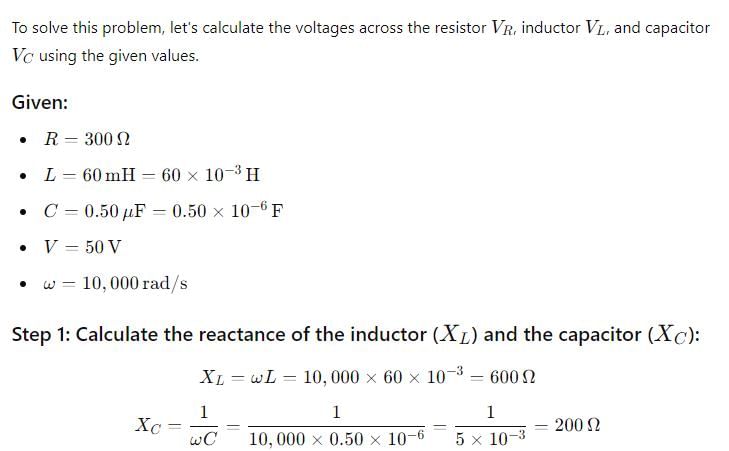
Find the total voltage applied in a series RLC circuit when i=3mA, VL=30V, VC=18V and R=1000 ohms.
13.95V
2 32.67V
3 6.67V
4 51V
2
3
4
|
|
Nikita Singh answered |
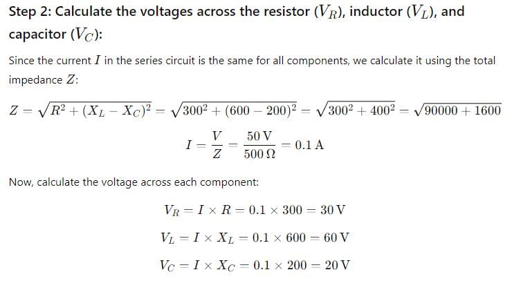
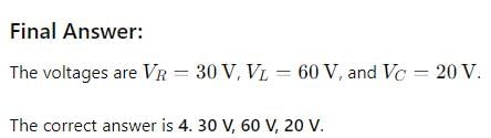
Explanation: Total voltage= VR+VL+VC.
VR=1000x3x10-3=3V.
Therefore, total voltage = 30+18+3=51V.
VR=1000x3x10-3=3V.
Therefore, total voltage = 30+18+3=51V.
Ratio  is equal to
- a)C
- b)L
- c)R
- d)Q
Correct answer is option 'D'. Can you explain this answer?
Ratio is equal to
is equal toa)
C
b)
L
c)
R
d)
Q

|
Shubham Rajput answered |
It is Q i.e. quality factor
A 1.0 mH inductance, a10μF capacitance and a 5.0 ohm resistance are connected series to an a.c. source. It is found that inductor and the capacitor show equal reactance. The reactance should be nearest to:- a)10 ohm
- b)32 ohm
- c)3.2 ohm
- d)100 ohm
Correct answer is option 'A'. Can you explain this answer?
A 1.0 mH inductance, a10μF capacitance and a 5.0 ohm resistance are connected series to an a.c. source. It is found that inductor and the capacitor show equal reactance. The reactance should be nearest to:
a)
10 ohm
b)
32 ohm
c)
3.2 ohm
d)
100 ohm
|
|
Nikita Singh answered |
From the formula we get,
XL=XC
ωL=1/ωC
⇒ω2=1/LC
⇒ω=1/√Lc
⇒ω=1/√10-3x10-5
⇒ω=104
We also know that,
XL=ωL
⇒XL=104x10-3
⇒XL=10 Ω
Therefore,XL=XC=10Ω
XL=XC
ωL=1/ωC
⇒ω2=1/LC
⇒ω=1/√Lc
⇒ω=1/√10-3x10-5
⇒ω=104
We also know that,
XL=ωL
⇒XL=104x10-3
⇒XL=10 Ω
Therefore,XL=XC=10Ω
L/R has dimensions same as that of- a)Reactance
- b)Capacitance
- c)Resistance
- d)Time
Correct answer is option 'D'. Can you explain this answer?
L/R has dimensions same as that of
a)
Reactance
b)
Capacitance
c)
Resistance
d)
Time
|
|
Pooja Mehta answered |
First of all we have to find out dimension of L and R .
We know, relation L answer energy is E = 1/2Li^2
so, dimension of L = dimension of energy/dimension of i2
= [ML2T⁻2]/[A2] = [ML2T⁻2A⁻2]
Similarly we know, relation between R and energy is E = i2Rt
So, dimension of R = dimension of E/dimension of i2t
= [ML2T⁻2][A2T] = [ML2T⁻2A⁻2]
Now, dimension of L/R = dimension of L/dimension of R
= [ML2T⁻2A⁻2][ML2T⁻2A⁻2] = [T]
Hence, answer is [T]
A pure resistance R, pure capacitance C and pure inductance L are connected in series and the impedance of the circuit at resonance is Z0. If they are connected in parallel to each other, the maximum impedance at resonance will be:- a)Less than R
- b)dependent on the values of C and L
- c)Equal to Z0
- d)More than R
Correct answer is option 'C'. Can you explain this answer?
A pure resistance R, pure capacitance C and pure inductance L are connected in series and the impedance of the circuit at resonance is Z0. If they are connected in parallel to each other, the maximum impedance at resonance will be:
a)
Less than R
b)
dependent on the values of C and L
c)
Equal to Z0
d)
More than R
|
|
Gaurav Kumar answered |
If series LCR circuit is present then z={R2+(xl-xc)2}1/2
if resonance is present then XC=CL or VC=CL then Z= Zo
if LCR circuit is in parallel form then in which circuit resonance is also present firstly 1/Z ={(1/R)2+ ((1/xc) –(1/xl))2}1/2 and in resonance conditions XC=CL according to this Z= Zo then option C is the correct answer
if resonance is present then XC=CL or VC=CL then Z= Zo
if LCR circuit is in parallel form then in which circuit resonance is also present firstly 1/Z ={(1/R)2+ ((1/xc) –(1/xl))2}1/2 and in resonance conditions XC=CL according to this Z= Zo then option C is the correct answer
If a resistor is connected across the voltage source and the frequency of voltage and current wave form is 50Hz, then what is frequency of instantaneous power- a)0 Hz.
- b)100 Hz.
- c) 50 Hz.
- d)150 Hz.
Correct answer is option 'B'. Can you explain this answer?
If a resistor is connected across the voltage source and the frequency of voltage and current wave form is 50Hz, then what is frequency of instantaneous power
a)
0 Hz.
b)
100 Hz.
c)
50 Hz.
d)
150 Hz.

|
Ayush Joshi answered |
 ]
]Therefore, frequency is doubled for the instantaneous power so, frequency of instantaneous power is 100Hz.
When an emf E = 7cos wt is applied across a circuit, the current is I = 5coswt. What is the power factor for the circuit?- a)infinite
- b)3/4
- c)zero
- d)1
Correct answer is option 'D'. Can you explain this answer?
When an emf E = 7cos wt is applied across a circuit, the current is I = 5coswt. What is the power factor for the circuit?
a)
infinite
b)
3/4
c)
zero
d)
1
|
|
Hansa Sharma answered |
Since E and I are in the same phase.
Therefore, phase difference will be 0 and since power factor= cosx (where x= phase difference) and x =0
therefore, cos x or power factor will be =1
Therefore, phase difference will be 0 and since power factor= cosx (where x= phase difference) and x =0
therefore, cos x or power factor will be =1
The average power dissipation in pure inductance is:- a)

- b)2LI2
- c)zero
- d)

Correct answer is option 'C'. Can you explain this answer?
The average power dissipation in pure inductance is:
a)
b)
2LI2
c)
zero
d)
|
|
Ayush Joshi answered |
Zero .. power = Irms Vrms cosǿ... where ǿ is angle between volatage and current vector... For pure inductance circuit the ǿ=90.. thus power is zero as cos90 is 0
When Ø is the phase difference, what is the power factor?- a)tan Ø
- b)cosh Ø
- c)cos Ø
- d)sin Ø
Correct answer is option 'C'. Can you explain this answer?
When Ø is the phase difference, what is the power factor?
a)
tan Ø
b)
cosh Ø
c)
cos Ø
d)
sin Ø
|
|
T.ttttt answered |
Cos Ø is called a power factor that indicates what fraction of [(Voltage V) x (Current I)] becomes the useful power. Most electric circuits have resistance and inductance. In such electric circuit, the current lags the voltage by the phase difference.
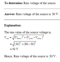
In an L-R-C series circuit, the rms voltage across the resistor is 30.0 V, across the capacitor it is 90.0 V, and across the inductor it is 50.0 V. Rms voltage of the source is- a)60.0 V
- b)50.0 V
- c)65.0 V
- d)5.0 V
Correct answer is option 'A'. Can you explain this answer?
In an L-R-C series circuit, the rms voltage across the resistor is 30.0 V, across the capacitor it is 90.0 V, and across the inductor it is 50.0 V. Rms voltage of the source is
a)
60.0 V
b)
50.0 V
c)
65.0 V
d)
5.0 V
|
|
Rajat Kapoor answered |
This Question Answer is
A sinusoidal voltage of peak value 283 V and frequency 50 Hz is applied to a series LCR circuit in which R = 3 Ω, L = 25.48 mH, and C = 796 μF. Power dissipated in the circuit; and the power factor are- a)4000 W, 0.4
- b)4800 W, 0.6
- c)4400 W, 0.6
- d)3800 W, 0.6
Correct answer is option 'B'. Can you explain this answer?
A sinusoidal voltage of peak value 283 V and frequency 50 Hz is applied to a series LCR circuit in which R = 3 Ω, L = 25.48 mH, and C = 796 μF. Power dissipated in the circuit; and the power factor are
a)
4000 W, 0.4
b)
4800 W, 0.6
c)
4400 W, 0.6
d)
3800 W, 0.6
|
|
Nandini Iyer answered |
Angular frequency of the ac signal w=2πν
∴ w=2π(50)=100π
Capacitive reactance Xc=1/wC
∴ Xc=1/(100π×786×10−6)=4Ω
Inductive reactance XL=wL
∴ XL=100π×(25.48×10−3)=8Ω
Impedance of the circuit Z=√[R2+(XL−Xc)2]
∴ Z=√[32+(8−4)2]=5Ω
Phase difference ϕ=tan−1[(XL−Xc)R]
Or ϕ=tan−1((8−4)/3)=tan−1(4/3)
⟹ ϕ=53.13o
Power factor cosϕ=cos53.13o=0.6
Power dissipated in the circuit
P=Iv2R
Now, Iv=I0/√2=E0/√2Z=283/(1.414×5)=40A
∴P=Iv2R=(40)2×3=4800 watt
What is the average power consumed/cycle in ideal capacitor.- a)infinite
- b)0
- c)EvIv
- d)cannot calculate it
Correct answer is option 'B'. Can you explain this answer?
What is the average power consumed/cycle in ideal capacitor.
a)
infinite
b)
0
c)
EvIv
d)
cannot calculate it
|
|
Prateek Jain answered |
Explanation:
In an ideal capacitor, there is no power dissipation as there is no resistance in the circuit. Therefore, the average power consumed per cycle is zero. This can be explained by the following points:
- An ideal capacitor is a passive component that stores energy in an electric field between its plates.
- When a capacitor is connected to a voltage source, it charges up to the source voltage and stores energy in the electric field.
- During the charging process, current flows into the capacitor, but there is no power dissipation as there is no resistance in the circuit.
- Once the capacitor is fully charged, there is no current flow and hence no power consumption.
- During discharge, the capacitor releases the stored energy and current flows out of the capacitor, but again there is no power dissipation as there is no resistance in the circuit.
- This charging and discharging process repeats itself in an AC circuit, but the average power consumed per cycle is zero as there is no power dissipation.
Therefore, the correct answer is option 'B' which states that the average power consumed per cycle in an ideal capacitor is zero.
A light bulb is rated at 50W for a 220 V supply. The resistance of the bulb, the peak voltage of the source and the rms current through the bulb are- a)768 ΩΩ, 391 V, 0.297A
- b)968 ΩΩ, 311 V, 0.227A
- c)468 ΩΩ, 411 V, 0.267A
- d)968 ΩΩ, 350 V, 0.327A
Correct answer is option 'B'. Can you explain this answer?
A light bulb is rated at 50W for a 220 V supply. The resistance of the bulb, the peak voltage of the source and the rms current through the bulb are
a)
768 ΩΩ, 391 V, 0.297A
b)
968 ΩΩ, 311 V, 0.227A
c)
468 ΩΩ, 411 V, 0.267A
d)
968 ΩΩ, 350 V, 0.327A
|
|
Harsh Desai answered |
The power rating of a light bulb is given as 50W, and it is connected to a 220V supply. We need to determine the resistance of the bulb, the peak voltage of the source, and the rms current through the bulb.
To find the resistance of the bulb, we can use the formula:
Resistance (R) = (Voltage (V))^2 / Power (P)
Substituting the given values:
R = (220V)^2 / 50W
R = 48400V^2 / 50W
R = 968Ω
Therefore, the resistance of the bulb is 968Ω.
To find the peak voltage of the source, we know that the peak voltage is equal to the root mean square (rms) voltage multiplied by the square root of 2. So, we can calculate the peak voltage using the formula:
Peak Voltage (Vp) = rms Voltage (Vrms) * √2
Substituting the given value:
Vp = 220V * √2
Vp = 220V * 1.414
Vp = 391V
Therefore, the peak voltage of the source is 391V.
Lastly, to find the rms current through the bulb, we can use the formula:
Power (P) = (Current (I))^2 * Resistance (R)
Substituting the given values:
50W = (I)^2 * 968Ω
Rearranging the equation, we get:
(I)^2 = 50W / 968Ω
(I)^2 = 0.0516A^2
Taking the square root of both sides, we find:
I = √0.0516A^2
I = 0.227A
Therefore, the rms current through the bulb is 0.227A.
In summary, the resistance of the bulb is 968Ω, the peak voltage of the source is 391V, and the rms current through the bulb is 0.227A. Thus, option B is the correct answer.
Q factor is- a)

- b)αR
- c)

- d)αR2
Correct answer is option 'A'. Can you explain this answer?
Q factor is
a)
b)
αR
c)
d)
αR2
|
|
Divey Sethi answered |
Q-factor: In LCR Circuit, the ratio of resonance frequency to the difference of its neighbouring frequencies so that their corresponding current is 1/√2 times of the peak value, is called Q-factor of the circuit.
Formula: Q=(1/R) √(L/C)
So, Q ∝1/R
Conditions for the large value of Q factor:
(i) Value of CL should be large.
(ii) Value of R should be less.
Formula: Q=(1/R) √(L/C)
So, Q ∝1/R
Conditions for the large value of Q factor:
(i) Value of CL should be large.
(ii) Value of R should be less.
If the instantaneous current in a circuit is given by i = 2 cos (ωt + φ) A, the rms value of the current is
- a)√2 A
- b)2√2 A
- c)2 A
- d)0 A
Correct answer is option 'A'. Can you explain this answer?
If the instantaneous current in a circuit is given by i = 2 cos (ωt + φ) A, the rms value of the current is
a)
√2 A
b)
2√2 A
c)
2 A
d)
0 A
|
|
Nikita Singh answered |
i=2cost
=Imcost
So, Im=2amp
IRMS=Im/√2
=2/√2
=√2amp
=Imcost
So, Im=2amp
IRMS=Im/√2
=2/√2
=√2amp

At resonance the current in an LCR circuit- a)is maximum
- b)is local minimum
- c)is zero
- d)is minimum
Correct answer is option 'A'. Can you explain this answer?
At resonance the current in an LCR circuit
a)
is maximum
b)
is local minimum
c)
is zero
d)
is minimum
|
|
Harsh Singhal answered |
Current is max.bcz impedance is minimum
In a series RCL circuit at resonance the applied ac voltage is 220 V. The potential drop across the inductance is 110V, what is the potential drop across the capacitor?- a)220 V
- b)220 √2 V
- c)110 √2 V
- d)110 V
Correct answer is option 'D'. Can you explain this answer?
In a series RCL circuit at resonance the applied ac voltage is 220 V. The potential drop across the inductance is 110V, what is the potential drop across the capacitor?
a)
220 V
b)
220 √2 V
c)
110 √2 V
d)
110 V
|
|
Nandini Iyer answered |
At resonance, the potential drop across the capacitance is equal and opposite to that of inductance i.e. 110V.
You have a special light bulb with a very delicate wire filament. The wire will break if the current in it ever exceeds 1.50 A, even for an instant. What is the largest root-mean-square current you can run through this bulb?- a)1.46 A
- b)1.06 A
- c)1.26 A
- d)1.56 A
Correct answer is option 'B'. Can you explain this answer?
You have a special light bulb with a very delicate wire filament. The wire will break if the current in it ever exceeds 1.50 A, even for an instant. What is the largest root-mean-square current you can run through this bulb?
a)
1.46 A
b)
1.06 A
c)
1.26 A
d)
1.56 A
|
|
Lavanya Menon answered |
Given,
We are given the current I=1.5Am where the wire will break.
We are asked to determine the root mean square of the current Irms. The maximum current here represents the current that just after it the wire will break. The maximum value of the current is the amplitude of the current wave and it should be larger than the root mean square of the current. Using equation, we can get the Irms in the form,
Irms = Imax/√2
The term, 1/√2, times any factor represents the root mean square of this factor, Now, plug the value for Imax into equation 1 and get Irms
Irms=Imax/√2
=1.5A/√2
=1.06A.
The impedance of a 10 microfarad capacitor for 50 Hz ac is:
- a)2 ohm
- b)1000 ohm
- c)1000 / π ohm
- d)20 ohm
Correct answer is option 'C'. Can you explain this answer?
The impedance of a 10 microfarad capacitor for 50 Hz ac is:
a)
2 ohm
b)
1000 ohm
c)
1000 / π ohm
d)
20 ohm
|
|
Hansa Sharma answered |
Impedance(XC)=1/ωC
=1/ 2πfC
=1/2πx50x10x10-6
=106/1000π
XC=103/π=(1000/π) Ω
=1/ 2πfC
=1/2πx50x10x10-6
=106/1000π
XC=103/π=(1000/π) Ω


In purely inductive circuits, the current:- a)lags behind voltage by π/2
- b)lead the voltage by π/2
- c)is in phase with the voltage
- d)none of the above
Correct answer is option 'A'. Can you explain this answer?
In purely inductive circuits, the current:
a)
lags behind voltage by π/2
b)
lead the voltage by π/2
c)
is in phase with the voltage
d)
none of the above

|
Bs Academy answered |
Explanation:
- Inductive Circuits:
In purely inductive circuits, the current lags behind the voltage by π/2 (90 degrees). This is because in an inductive circuit, the voltage leads the current due to the phase shift caused by the presence of inductance.
- Phase Relationship:
When an alternating current passes through an inductor, a back EMF is induced in the coil which opposes the flow of current. This causes the current to lag behind the voltage in an inductive circuit.
- Mathematical Representation:
Mathematically, this phase shift can be represented as a phase angle of π/2 (90 degrees) between the current and voltage in a purely inductive circuit.
- Conclusion:
Therefore, in purely inductive circuits, the current lags behind the voltage by π/2 due to the inherent characteristics of inductors to oppose changes in current flow.
What is phase angle given R = 10, Z = 20- a)30°
- b)45°
- c)60°
- d)90°
Correct answer is option 'C'. Can you explain this answer?
What is phase angle given R = 10, Z = 20
a)
30°
b)
45°
c)
60°
d)
90°

|
Manvi Goyal answered |
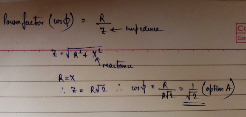
Cos x (power factor) = R/Z
= 10/20
=1/2
x= 60
= 10/20
=1/2
x= 60
In which of the following cases the power factor is not equal to 1- a)XC = XL = 0
- b)XL > XC
- c)XL = XC
- d)Z = R
Correct answer is option 'B'. Can you explain this answer?
In which of the following cases the power factor is not equal to 1
a)
XC = XL = 0
b)
XL > XC
c)
XL = XC
d)
Z = R
|
|
Manoj Chauhan answered |
Explanation:
Power factor is defined as the ratio of real power (P) to apparent power (S). It is a measure of how efficiently the electrical power is being used. A power factor of 1 means that all the electrical power being supplied is being used efficiently without any wastage. In the following cases, the power factor is not equal to 1:
Case b) XL XC:
In this case, the impedance of the circuit is given by Z = XL - XC. If XL > XC, then the circuit is said to be inductive and if XC > XL, then the circuit is said to be capacitive. In either case, the power factor is not equal to 1. For an inductive circuit, the power factor is lagging (less than 1) and for a capacitive circuit, the power factor is leading (greater than 1). This is because in an inductive circuit, the current lags behind the voltage and in a capacitive circuit, the current leads the voltage.
Case c) XL = XC:
If XL = XC, then the circuit is said to be in resonance. In this case, the impedance of the circuit is purely resistive and there is no reactive component. The power factor is equal to 1 in this case, as all the electrical power being supplied is being used efficiently without any wastage.
Case d) Z = R:
If the impedance of the circuit is purely resistive, then the power factor is equal to 1. This is because there is no reactive component and all the electrical power being supplied is being used efficiently without any wastage.
Case a) XC = XL = 0:
If both XC and XL are zero, then the circuit is purely resistive and the power factor is equal to 1. This is because there is no reactive component and all the electrical power being supplied is being used efficiently without any wastage.
Therefore, the correct answer is option b) XL XC, as the power factor is not equal to 1 in this case.
In the free oscillations of an LC circuit, the sum of energies stored in the capacitor and the inductor.- a)varies cubically with time
- b)varies linearly with time
- c)varies as square of time
- d)is constant in time
Correct answer is option 'D'. Can you explain this answer?
In the free oscillations of an LC circuit, the sum of energies stored in the capacitor and the inductor.
a)
varies cubically with time
b)
varies linearly with time
c)
varies as square of time
d)
is constant in time
|
|
Om Desai answered |
At any time, t
energy stored in capacitor, EC=q2/2C
Total energy stored in C and L at any time t
E=EC+EL
E=(q2/2C)+(LI2/2)
If q=q0sinωt
I=dq/dt=q0cosωtω=ωq0cosωt
Put in (i), E=[(q0sinωt)2/2C] + L(ωq0cosωt)2/2
E=(q02/2C) sin2ωt+(q02/2)cos2ωt.ω2L
But ω2=12/LC
∴E=(q02/2C) sin2ωt+(q02/2) (L/LC) cos2ωt
=q02/2C(sin2ωt+cos2ωt)
=q02/2C= constant in time.
Measure of sharpness in an ac circuit is given by- a)Power ratio
- b)Quality factor
- c)Power factor
- d)Quality ratio
Correct answer is option 'B'. Can you explain this answer?
Measure of sharpness in an ac circuit is given by
a)
Power ratio
b)
Quality factor
c)
Power factor
d)
Quality ratio
|
|
Ritika Sengupta answered |
Sharpness in an AC circuit is measured by the Quality Factor.
Quality Factor:
The quality factor or Q-factor is defined as the ratio of the energy stored in a system to the energy dissipated in the system per cycle of oscillation. It is a dimensionless quantity and is represented by the symbol Q.
Mathematically, Q-factor is given by the ratio of the resonant frequency to the bandwidth of the circuit.
Q-factor = Resonant frequency / Bandwidth
The higher the Q-factor, the sharper the resonance peak of the circuit. A high Q-factor means that the circuit can store energy efficiently and can oscillate for a longer time without losing energy.
Sharpness in an AC Circuit:
In an AC circuit, the sharpness is determined by the Q-factor of the circuit. The Q-factor of the circuit can be defined as the ratio of the energy stored in the circuit to the energy lost per cycle of oscillation. The sharpness of the circuit is directly proportional to the Q-factor of the circuit.
In an AC circuit, the sharpness is determined by the amount of energy stored in the circuit and the amount of energy lost per cycle of oscillation. The more energy the circuit can store, the sharper the resonance peak of the circuit. The less energy the circuit loses, the sharper the resonance peak of the circuit.
Thus, the quality factor is the measure of sharpness in an AC circuit.
In a ac circuit with capacitance, the current- a)leads by 90 degree
- b)lags by 90 degree
- c)lags by 180 degree
- d)leads by 180 degree
Correct answer is option 'A'. Can you explain this answer?
In a ac circuit with capacitance, the current
a)
leads by 90 degree
b)
lags by 90 degree
c)
lags by 180 degree
d)
leads by 180 degree
|
|
Harsh Singhal answered |
For capacitor current lead by 90 degree with voltage & for inductive voltage leads by 90 degree
Find the true power given apparent power = 10 W and power factor = 0.5- a)0.5 W
- b)0.05 W
- c)5 W
- d)50 W
Correct answer is option 'C'. Can you explain this answer?
Find the true power given apparent power = 10 W and power factor = 0.5
a)
0.5 W
b)
0.05 W
c)
5 W
d)
50 W

|
.mie. answered |
Ys.. C is correct opt... as ... true powr = apparent powr × powr factor.. here apparent power =10W and power factor=0.5 so true power =10×0.5 = 5W
For a series LCR circuit the input impedance at resonancea)equals the resistanceωLb)equals the resistance Rc)equals the resistance1/ωCd)equals the resistanceR+jωLCorrect answer is option 'B'. Can you explain this answer?

|
Anonymous answered |
I think answer is b
Because
At resonance
Xl = Xc
Z = √R² + (Xl - Xc) ²
Xl = X c
Z = R
Correct me if I am wrong
Because
At resonance
Xl = Xc
Z = √R² + (Xl - Xc) ²
Xl = X c
Z = R
Correct me if I am wrong
Chapter doubts & questions for Alternating Current - Physics Class 12 2025 is part of Class 12 exam preparation. The chapters have been prepared according to the Class 12 exam syllabus. The Chapter doubts & questions, notes, tests & MCQs are made for Class 12 2025 Exam. Find important definitions, questions, notes, meanings, examples, exercises, MCQs and online tests here.
Chapter doubts & questions of Alternating Current - Physics Class 12 in English & Hindi are available as part of Class 12 exam.
Download more important topics, notes, lectures and mock test series for Class 12 Exam by signing up for free.
Physics Class 12
127 videos|452 docs|99 tests
|
|
© EduRev
|
Education Revolution
|


|


Signup to see your scores
go up within 7 days!
Access 1000+ FREE Docs, Videos and Tests
Takes less than 10 seconds to signup