


All Exams >
JEE >
35 Years Chapter wise Previous Year Solved Papers for JEE >
All Questions
All questions of Electromagnetic Induction and Alternating Current for JEE Exam
L, C and R represent the physical quantities, inductance, capacitance and resistance respectively. The combination(s) which have the dimensions of frequency are - a)1/RC
- b)R/L
- c)

- d)C/L
Correct answer is option 'B'. Can you explain this answer?
L, C and R represent the physical quantities, inductance, capacitance and resistance respectively. The combination(s) which have the dimensions of frequency are
a)
1/RC
b)
R/L
c)
d)
C/L

|
Notes Wala answered |
KEY CONCEPT : The magnetic field due to a current flowing in a wire of finite length is given by
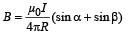
Applying the above formula for AB for finding the field at O, we get
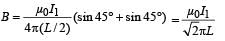
acting perpendicular to the plane of paper upwards
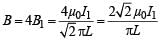
∴ The total magnetic field due to current flowing through ABCD is
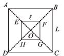
The total flux passing through the square EFGH
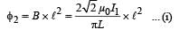
[∵ ℓ > L and therefore, B can be assumed constant for ℓ2]
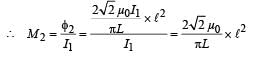
The flux through small square loop is directly proportional to the current passing through big square loop.
∴ φ2 ∝ I1 ⇒ φ = MI1 where M = Mutual Conductance


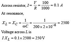
In the given circuit, the AC source has ω = 100 rad/s. Considering the inductor and capacitor to be ideal, the correct choice(s) is (are)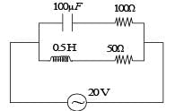
- a)The current through the circuit, I is 0.3 A.
- b)The current through the circuit, I is

- c)The voltage across 100 Ω resistor

- d)The voltage across 50 Ω resistor = 10 V
Correct answer is option 'A,C'. Can you explain this answer?
In the given circuit, the AC source has ω = 100 rad/s. Considering the inductor and capacitor to be ideal, the correct choice(s) is (are)
a)
The current through the circuit, I is 0.3 A.
b)
The current through the circuit, I is
c)
The voltage across 100 Ω resistor
d)
The voltage across 50 Ω resistor = 10 V
|
|
Lavanya Menon answered |
Impedance across AB
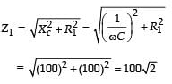
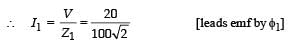
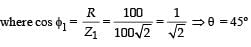
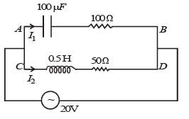
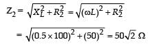
Impedance across CD is
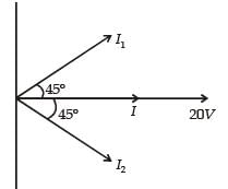
∴The current I from the circuit is
In an a.c. circuit the voltage applied is E = E0 sin ωt. The resulting current in the circuit is 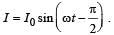 The power consumption in the circuit is given by
 - a)

- b)

- c)P = zero
- d)

Correct answer is option 'C'. Can you explain this answer?
In an a.c. circuit the voltage applied is E = E0 sin ωt. The resulting current in the circuit is The power consumption in the circuit is given by
The power consumption in the circuit is given by a)
b)
c)
P = zero
d)

|
Pioneer Academy answered |
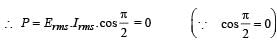
KEY CONCEPT : We know that power consumed in a.c. circuit is given by, 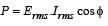
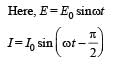
which implies that the phase difference, 
A series R– C circuit is connected to AC voltage source. Consider two cases; (A) when C is without a dielectric medium and (B) when C is filled with dielectric of constant 4.
The current IR through the resistor and voltage VC across the capacitor are compared in the two cases. Which of the following is/are true?- a)

- b)

- c)

- d)

Correct answer is option 'A,C'. Can you explain this answer?
A series R– C circuit is connected to AC voltage source. Consider two cases; (A) when C is without a dielectric medium and (B) when C is filled with dielectric of constant 4.
The current IR through the resistor and voltage VC across the capacitor are compared in the two cases. Which of the following is/are true?
The current IR through the resistor and voltage VC across the capacitor are compared in the two cases. Which of the following is/are true?
a)
b)
c)
d)

|
Vikas Saini answered |
When fiiled with a capacitor,capacitance increase Q=CV,if C increases then V decrease in case B,and same for current by V=IR
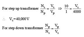
A thermal power plant produces electric power of 600 kW at 4000 V, which is to be transported to a place 20 km away from the power plant for consumers' usage. It can be transported either directly with a cable of large current carrying capacity or by using a combination of step-up and step-down transformers at the two ends. The drawback of the direct transmission is the large energy dissipation. In the method using transformers, the dissipation is much smaller. In this method , a step-up transformer is used at the plant side so that the current is reduced to a smaller value. At the consumers' end, a step-down transformer is used to supply power to the consumers at the specified lower voltage. It is reasonable to assume that the power cable is purely resistive and the transformers are ideal with power factor unity. All the currents and voltages mentioned are rms values.Q. In the method using the transformers, assume that the ratio of the number of turns in the primary to that in the secondary in the step-up transformer is 1 : 10. If the power to the consumers has to be supplied at 200 V, the ratio of the number of turns in the primary to that in the secondary in the stepdown transformer is- a)200 : 1
- b)150 : 1
- c)100 : 1
- d)50 : 1
Correct answer is option 'B'. Can you explain this answer?
A thermal power plant produces electric power of 600 kW at 4000 V, which is to be transported to a place 20 km away from the power plant for consumers' usage. It can be transported either directly with a cable of large current carrying capacity or by using a combination of step-up and step-down transformers at the two ends. The drawback of the direct transmission is the large energy dissipation. In the method using transformers, the dissipation is much smaller. In this method , a step-up transformer is used at the plant side so that the current is reduced to a smaller value. At the consumers' end, a step-down transformer is used to supply power to the consumers at the specified lower voltage. It is reasonable to assume that the power cable is purely resistive and the transformers are ideal with power factor unity. All the currents and voltages mentioned are rms values.
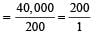
Q. In the method using the transformers, assume that the ratio of the number of turns in the primary to that in the secondary in the step-up transformer is 1 : 10. If the power to the consumers has to be supplied at 200 V, the ratio of the number of turns in the primary to that in the secondary in the stepdown transformer is
a)
200 : 1
b)
150 : 1
c)
100 : 1
d)
50 : 1

|
Rohit Yadav answered |
We know that P = V × I
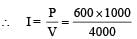
∴ I = 150 A
Total resistance = 0.4 × 20 = 8 Ω
Total resistance = 0.4 × 20 = 8 Ω
∴ Power dissipated as heat = I2R = (150)2 × 8
= 180,000W = 180 kW
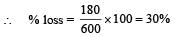
(b) is the correct option.
A thermal power plant produces electric power of 600 kW at 4000 V, which is to be transported to a place 20 km away from the power plant for consumers' usage. It can be transported either directly with a cable of large current carrying capacity or by using a combination of step-up and step-down transformers at the two ends. The drawback of the direct transmission is the large energy dissipation. In the method using transformers, the dissipation is much smaller. In this method , a step-up transformer is used at the plant side so that the current is reduced to a smaller value. At the consumers' end, a step-down transformer is used to supply power to the consumers at the specified lower voltage. It is reasonable to assume that the power cable is purely resistive and the transformers are ideal with power factor unity. All the currents and voltages mentioned are rms values.Q. If the direct transmission method with a cable of resistance 0.4 Ω km–1 is used, the power dissipation| (in %) during transmission is- a)20
- b)30
- c)40
- d)50
Correct answer is option 'A'. Can you explain this answer?
A thermal power plant produces electric power of 600 kW at 4000 V, which is to be transported to a place 20 km away from the power plant for consumers' usage. It can be transported either directly with a cable of large current carrying capacity or by using a combination of step-up and step-down transformers at the two ends. The drawback of the direct transmission is the large energy dissipation. In the method using transformers, the dissipation is much smaller. In this method , a step-up transformer is used at the plant side so that the current is reduced to a smaller value. At the consumers' end, a step-down transformer is used to supply power to the consumers at the specified lower voltage. It is reasonable to assume that the power cable is purely resistive and the transformers are ideal with power factor unity. All the currents and voltages mentioned are rms values.
Q. If the direct transmission method with a cable of resistance 0.4 Ω km–1 is used, the power dissipation| (in %) during transmission is
a)
20
b)
30
c)
40
d)
50

|
Krish Ghoshal answered |
(a) is the correct option.
A circular loop of radius 0.3 cm lies parallel to amuch bigger circular loop of radius 20 cm. The centre of the small loop is on the axis of the bigger loop. The distance between their centres is 15 cm. If a current of 2.0 A flows through the smaller loop, then the flux linked with bigger loop is- a)9.1 × 10⁻¹¹ weber
- b)6 × 10–11 weber
- c)3.3 × 10⁻¹¹ weber
- d)6.6 × 10⁻⁹ weber
Correct answer is option 'A'. Can you explain this answer?
A circular loop of radius 0.3 cm lies parallel to amuch bigger circular loop of radius 20 cm. The centre of the small loop is on the axis of the bigger loop. The distance between their centres is 15 cm. If a current of 2.0 A flows through the smaller loop, then the flux linked with bigger loop is
a)
9.1 × 10⁻¹¹ weber
b)
6 × 10–11 weber
c)
3.3 × 10⁻¹¹ weber
d)
6.6 × 10⁻⁹ weber
|
|
Prasenjit Sen answered |
The magnetic field produced by the small loop at the position of the bigger loop can be calculated using the formula for the magnetic field at the center of a circular loop:
B = (μ₀ * I * R²) / (2 * (R² + r²)^(3/2))
Where B is the magnetic field, μ₀ is the permeability of free space, I is the current, R is the radius of the loop producing the field, and r is the distance between the center of the producing loop and the point where the field is measured.
Plugging in the values, we get:
B = (4π * 10^(-7) * 2.0 * (0.3 * 10^(-2))²) / (2 * ( (0.3 * 10^(-2))² + (20 * 10^(-2))²)^(3/2))
B ≈ 0.0627 μT (T = Tesla)
The flux linked with the bigger loop can then be calculated using the formula:
Φ = B * A
Where Φ is the flux, B is the magnetic field, and A is the area of the loop.
The area of the bigger loop can be calculated using the formula for the area of a circle:
A = π * R²
Plugging in the values, we get:
Φ = (0.0627 * 10^(-6)) * π * (20 * 10^(-2))²
Φ ≈ 0.0248 Wb (Wb = Weber)
Therefore, the flux linked with the bigger loop is approximately 0.0248 Weber.
A coil of wire having inductance and resistance has a conducting ring placed coaxially within it. The coil is connected to a battery at time t = 0, so that a time-dependent current l1(t) starts flowing through the coil. If I2(t) is the current induced in the ring, and B(t) is the magnetic field at the axis of the coil due to I1(t), then as a function of time (t > 0), the product I2(t) B(t)- a)increases with time
- b)decreases with time
- c)does not vary with time
- d)passes through a maximum
Correct answer is option `D`. Can you explain this answer?
A coil of wire having inductance and resistance has a conducting ring placed coaxially within it. The coil is connected to a battery at time t = 0, so that a time-dependent current l1(t) starts flowing through the coil. If I2(t) is the current induced in the ring, and B(t) is the magnetic field at the axis of the coil due to I1(t), then as a function of time (t > 0), the product I2(t) B(t)
a)
increases with time
b)
decreases with time
c)
does not vary with time
d)
passes through a maximum
|
|
Anirban Banerjee answered |
The current induced in the ring, I2(t), can be found using Faraday's law of electromagnetic induction. According to Faraday's law, the electromotive force (emf) induced in a conducting loop is equal to the rate of change of magnetic flux through the loop. Mathematically, it can be written as:
emf = -dΦ/dt
where emf is the induced electromotive force, Φ is the magnetic flux, and dt is the change in time.
In this case, the ring is placed coaxially within the coil, so the magnetic field at the axis of the coil, B(t), is directly proportional to the current flowing through the coil, I1(t). Mathematically, it can be written as:
B(t) = k * I1(t)
where k is a constant of proportionality.
The magnetic flux through the ring, Φ, is given by the equation:
Φ = B(t) * A
where A is the area enclosed by the ring.
Substituting the value of B(t) from the previous equation, we get:
Φ = k * I1(t) * A
Now, differentiating both sides of the equation with respect to time, we get:
dΦ/dt = k * d(I1(t))/dt * A
Since the emf induced in the ring is equal to -dΦ/dt, we can write:
emf = -k * d(I1(t))/dt * A
The emf induced in the ring is given by Ohm's law as:
emf = R2 * I2(t)
where R2 is the resistance of the ring and I2(t) is the current induced in the ring.
Setting the two equations for emf equal to each other, we get:
R2 * I2(t) = -k * d(I1(t))/dt * A
Now, rearranging the equation, we can solve for I2(t):
I2(t) = (-k * d(I1(t))/dt * A) / R2
Therefore, as a function of time (t), the current induced in the ring, I2(t), is given by:
I2(t) = (-k * d(I1(t))/dt * A) / R2
A short-circuited coil is placed in a time-varying magnetic field. Electrical power is dissipated due to the current induced in the coil. If the number of turns were to be quadrupled and the wire radius halved, the electrical power dissipated would be- a)halved
- b)the same
- c)doubled
- d)quadrupled
Correct answer is option 'B'. Can you explain this answer?
A short-circuited coil is placed in a time-varying magnetic field. Electrical power is dissipated due to the current induced in the coil. If the number of turns were to be quadrupled and the wire radius halved, the electrical power dissipated would be
a)
halved
b)
the same
c)
doubled
d)
quadrupled

|
Nandita Basak answered |
KEY CONCEPT :
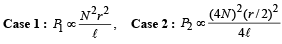
NOTE : When we decrease the radius of the wire, its length increases but volume remains the same]

∴ Power remains the same.
The SI unit of inductance, the henry, can be written as- a)weber/ampere
- b)volt-second/ampere
- c)joule/(ampere)2
- d)ohm-second
Correct answer is option 'A,B,C,D'. Can you explain this answer?
The SI unit of inductance, the henry, can be written as
a)
weber/ampere
b)
volt-second/ampere
c)
joule/(ampere)2
d)
ohm-second
|
|
Sravya Mukherjee answered |
The SI unit of inductance, the henry, can be expressed in multiple ways to provide a better understanding of its physical meaning. Let's break down the different representations of the henry:
- weber/ampere: The unit of inductance, the henry, is defined as the amount of inductance when the induced electromotive force is one volt in a circuit where the current is changing at a rate of one ampere per second. This can be written as weber/ampere, where weber is the unit of magnetic flux and ampere is the unit of current.
- volt-second/ampere: Another way to express the unit of inductance is volt-second/ampere. This representation highlights the relationship between the induced voltage (volt) and the rate of change of current (ampere/second) in an inductive circuit.
- joule/(ampere)^2: The unit of inductance can also be written as joule/(ampere)^2. This form emphasizes the energy stored in the magnetic field (joule) per square of current (ampere) in an inductive component.
- ohm-second: Inductance can also be represented as ohm-second, which reflects the opposition to the change in current flow in an inductive circuit. This is analogous to the resistance (ohm) in a resistive circuit, but in the case of inductance, it is a time-dependent quantity.
By understanding the various ways in which the unit of inductance, the henry, can be expressed, we can appreciate its significance in the behavior of inductive components in electrical circuits.
Statement-1 : A vertical iron rod has coil of wire wound over it at the bottom end. An alternating current flows in the coil. The rod goes through a conducting ring as shown in the figure. The ring can float at a certain height above the coil.
Statement-2 : In the above situation, a current is induced in the ring which interacts with the horizontal component of the magnetic field to produce an average force in the upward direction.- a)Statement-1 is True, Statement-2 is True; Statement-2 is a correct explanation for Statement-1
- b)Statement-1 is True, Statement-2 is True; Statement-2 is NOT a correct explanation for Statement-1
- c)Statement-1 is True, Statement-2 is False
- d)Statement-1 is False, Statement-2 is True.
Correct answer is option 'A'. Can you explain this answer?
Statement-1 : A vertical iron rod has coil of wire wound over it at the bottom end. An alternating current flows in the coil. The rod goes through a conducting ring as shown in the figure. The ring can float at a certain height above the coil.
Statement-2 : In the above situation, a current is induced in the ring which interacts with the horizontal component of the magnetic field to produce an average force in the upward direction.
Statement-2 : In the above situation, a current is induced in the ring which interacts with the horizontal component of the magnetic field to produce an average force in the upward direction.
a)
Statement-1 is True, Statement-2 is True; Statement-2 is a correct explanation for Statement-1
b)
Statement-1 is True, Statement-2 is True; Statement-2 is NOT a correct explanation for Statement-1
c)
Statement-1 is True, Statement-2 is False
d)
Statement-1 is False, Statement-2 is True.
|
|
Ipsita Deshpande answered |
Explanation:
Statement-1: A vertical iron rod has coil of wire wound over it at the bottom end. An alternating current flows in the coil. The rod goes through a conducting ring as shown in the figure. The ring can float at a certain height above the coil.
- In this statement, it describes a setup where there is a vertical iron rod with a coil of wire at the bottom end. An alternating current flows through the coil, creating a magnetic field around the rod.
- The conducting ring placed above the coil can float at a certain height due to the interaction of magnetic fields.
Statement-2: In the above situation, a current is induced in the ring which interacts with the horizontal component of the magnetic field to produce an average force in the upward direction.
- This statement explains that when the alternating current flows through the coil, it induces a current in the conducting ring.
- The induced current in the ring interacts with the horizontal component of the magnetic field produced by the coil, resulting in an average force in the upward direction on the ring.
Therefore, both Statement-1 and Statement-2 are true in this scenario. Statement-2 provides a correct explanation for the phenomenon described in Statement-1. The induced current in the ring interacting with the magnetic field is what causes the ring to float at a certain height above the coil.
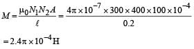
Two coaxial solenoids are made by winding thin insulated wire over a pipe of cross-sectional area A = 10 cm2 and length = 20 cm. If one of the solenoid has 300 turns and the other 400 turns, their mutual inductance is(μ0 = 4π × 10 –7 Tm A–1)- a)2.4π × 10–5 H
- b)4.8π × 10–4 H
- c)4.8π × 10–5 H
- d)2.4π × 10–4 H
Correct answer is option 'D'. Can you explain this answer?
Two coaxial solenoids are made by winding thin insulated wire over a pipe of cross-sectional area A = 10 cm2 and length = 20 cm. If one of the solenoid has 300 turns and the other 400 turns, their mutual inductance is
(μ0 = 4π × 10 –7 Tm A–1)
a)
2.4π × 10–5 H
b)
4.8π × 10–4 H
c)
4.8π × 10–5 H
d)
2.4π × 10–4 H

|
Devansh Joshi answered |
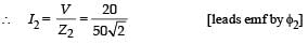
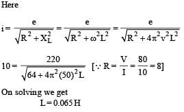
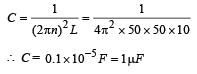
In a series LCR circuit R = 200Ω and the voltage and the frequency of the main supply is 220V and 50 Hz respectively.
On taking out the capacitance from the circuit the current lags behind the voltage by 30°. On taking out the inductor from the circuit the current leads the voltage by 30°. The power dissipated in the LCR circuit is- a)305 W
- b)210 W
- c)Zero W
- d)242 W
Correct answer is option 'D'. Can you explain this answer?
In a series LCR circuit R = 200Ω and the voltage and the frequency of the main supply is 220V and 50 Hz respectively.
On taking out the capacitance from the circuit the current lags behind the voltage by 30°. On taking out the inductor from the circuit the current leads the voltage by 30°. The power dissipated in the LCR circuit is
On taking out the capacitance from the circuit the current lags behind the voltage by 30°. On taking out the inductor from the circuit the current leads the voltage by 30°. The power dissipated in the LCR circuit is
a)
305 W
b)
210 W
c)
Zero W
d)
242 W
|
|
Moumita Dey answered |
In a series LCR circuit, R represents the resistance of the circuit. The value of R is given as 200.
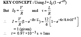
A resistor ‘R’ and 2µF capacitor in series is connected through a switch to 200 V direct supply. Across the capacitor is a neon bulb that lights up at 120 V. Calculate the value of R to make the bulb light up 5 s after the switch has been closed. (log10 2.5 = 0.4)- a)1.7 × 10⁵ Ω
- b)2.7 × 10⁶ Ω
- c)3.3 × 10⁷ Ω
- d)1.3 × 10⁴ Ω
Correct answer is option 'B'. Can you explain this answer?
A resistor ‘R’ and 2µF capacitor in series is connected through a switch to 200 V direct supply. Across the capacitor is a neon bulb that lights up at 120 V. Calculate the value of R to make the bulb light up 5 s after the switch has been closed. (log10 2.5 = 0.4)
a)
1.7 × 10⁵ Ω
b)
2.7 × 10⁶ Ω
c)
3.3 × 10⁷ Ω
d)
1.3 × 10⁴ Ω

|
Dipanjan Majumdar answered |
We have, V = V0 (1 – e–t/RC)
⇒ 120 = 200 (1 - e-t / RC)
⇒ t = RC in (2.5)
⇒ 120 = 200 (1 - e-t / RC)
⇒ t = RC in (2.5)
⇒ R = 2.71 × 10⁶ W
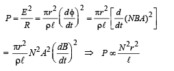
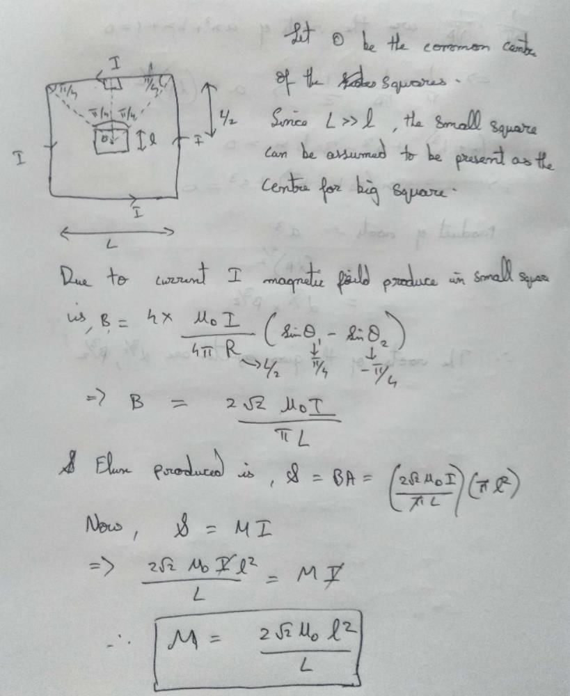
A small square loop of wire of side l is placed inside a large square loop of wire of side L(L>>l). The loops are co-planar and their centres coincide. The mutual inductance of the system is proportional to- a)l/L
- b)l2/L
- c)L/l
- d)L2/l
Correct answer is option 'B'. Can you explain this answer?
A small square loop of wire of side l is placed inside a large square loop of wire of side L(L>>l). The loops are co-planar and their centres coincide. The mutual inductance of the system is proportional to
a)
l/L
b)
l2/L
c)
L/l
d)
L2/l
|
|
Ram Mohith answered |

The phase difference between the alternating current and emf is π/2. Which of the following cannot be the constituent of the circuit?- a)R, L
- b)C alone
- c)L alone
- d)L, C
Correct answer is option 'A'. Can you explain this answer?
The phase difference between the alternating current and emf is π/2. Which of the following cannot be the constituent of the circuit?
a)
R, L
b)
C alone
c)
L alone
d)
L, C
|
|
Shalini Yadav answered |
The phase difference between the alternating current (AC) and electromotive force (EMF) depends on the type of circuit elements present. In an ideal inductor or capacitor, the phase difference between the AC voltage and current is 90 degrees. In a resistor, there is no phase difference as the voltage and current are in phase. In a circuit with a combination of resistors, inductors, and capacitors, the phase difference can vary depending on the specific values of the components.
A thin circular ring of area A is held perpendicular to a uniform magnetic field of induction B. A small cut is made in the ring and a galvanometer is connected across the ends such that the total resistance of the circuit is R. When the ring is suddenly squeezed to zero area, the charge flowing through the galvanometer is- a)BR/A
- b)AB/R
- c)ABR
- d)B2A/R2
Correct answer is option 'B'. Can you explain this answer?
A thin circular ring of area A is held perpendicular to a uniform magnetic field of induction B. A small cut is made in the ring and a galvanometer is connected across the ends such that the total resistance of the circuit is R. When the ring is suddenly squeezed to zero area, the charge flowing through the galvanometer is
a)
BR/A
b)
AB/R
c)
ABR
d)
B2A/R2
|
|
Tanvi Iyer answered |
Explanation:
To understand why the correct answer is option B, let's analyze the scenario step by step.
Step 1: Initial State
In the initial state, we have a thin circular ring of area A held perpendicular to a uniform magnetic field of induction B. The magnetic field lines pass through the area of the ring. Since the ring is thin, the magnetic field is almost uniform across its area.
Step 2: Squeezing the Ring
When the ring is suddenly squeezed to zero area, it means that the area of the ring is reduced to zero. As a result, the magnetic field lines passing through the ring are also reduced to zero.
Step 3: Induced EMF
According to Faraday's law of electromagnetic induction, a change in the magnetic field induces an electromotive force (EMF) in a closed loop. In this case, when the ring is squeezed to zero area, the change in magnetic field induces an EMF in the ring.
Step 4: Current Flow
The induced EMF causes a current to flow in the closed loop. In this case, the closed loop consists of the cut made in the ring and the galvanometer connected across its ends. The total resistance of the circuit is R.
Step 5: Application of Ohm's Law
To determine the charge flowing through the galvanometer, we need to apply Ohm's law. Ohm's law states that the current flowing through a conductor is directly proportional to the voltage across it and inversely proportional to its resistance.
In this case, the voltage across the circuit is the induced EMF, which is directly proportional to the change in magnetic field. The resistance of the circuit is R. Therefore, according to Ohm's law, the current flowing through the galvanometer is given by:
I = EMF / R
Step 6: Relationship between EMF and Magnetic Field
The induced EMF is directly proportional to the change in magnetic field. When the ring is squeezed to zero area, the magnetic field is reduced to zero. Therefore, the change in magnetic field is B.
Step 7: Final Answer
Substituting the values in the equation for current, we get:
I = B / R
Therefore, the charge flowing through the galvanometer is given by:
Q = I * t = (B / R) * t
Since the question does not provide any information about the time interval, we can assume it to be 1 second. Hence, the charge flowing through the galvanometer is:
Q = B / R
And this matches with option B, which is the correct answer.
Which tile is used for bathroom?
- a)undulated tile
- b)Anti slippery
- c)Smooth tile
- d)Polished tile
Correct answer is option 'B'. Can you explain this answer?
Which tile is used for bathroom?
a)
undulated tile
b)
Anti slippery
c)
Smooth tile
d)
Polished tile
|
|
Ritu Singh answered |
Bathroom tile have rough surface which kind of wavy (undulated) to increase friction.
Hence B
In an AC generator, a coil with N turns, all of the same area A and total resistance R, rotates with frequency ω in a magnetic field B. The maximum value of emf generated in the coil is- a)N.A.B.R.ω
- b)N.A.B
- c)N.A.B.R.
- d)N.A.B.ω
Correct answer is option 'D'. Can you explain this answer?
In an AC generator, a coil with N turns, all of the same area A and total resistance R, rotates with frequency ω in a magnetic field B. The maximum value of emf generated in the coil is
a)
N.A.B.R.ω
b)
N.A.B
c)
N.A.B.R.
d)
N.A.B.ω
|
|
Sanjana Mishra answered |
F in a magnetic field B. The magnetic field is perpendicular to the plane of the coil. The coil is connected to a load resistance RL.
When the coil rotates, the magnetic field induces an electromotive force (emf) in the coil. The induced emf can be calculated using Faraday's law of electromagnetic induction:
emf = -N * dΦ/dt
where N is the number of turns in the coil and dΦ/dt is the rate of change of magnetic flux through the coil.
The magnetic flux through the coil can be calculated using the equation:
Φ = B * A * cos(θ)
where B is the magnetic field strength, A is the area of the coil, and θ is the angle between the magnetic field and the normal to the coil's plane.
If the coil rotates with frequency f, the rate of change of magnetic flux can be expressed as:
dΦ/dt = B * A * d(cos(θ))/dt
= -B * A * ω * sin(ωt)
where ω = 2πf is the angular frequency of rotation.
Substituting this expression into the equation for emf, we get:
emf = N * B * A * ω * sin(ωt)
The load resistance RL is connected in series with the coil, so the current flowing through the circuit can be calculated using Ohm's law:
I = emf / (RL + R)
where I is the current flowing through the circuit.
Therefore, the current in the circuit depends on the angular frequency of rotation (ω), the number of turns in the coil (N), the magnetic field strength (B), the area of the coil (A), the load resistance (RL), and the total resistance of the coil (R).
Which is known as the temple town of tamilnadu
- a)Bhubaneswar
- b)kanchipuram
- c)srirangam
- d)kumbakkonam
Correct answer is option 'B'. Can you explain this answer?
Which is known as the temple town of tamilnadu
a)
Bhubaneswar
b)
kanchipuram
c)
srirangam
d)
kumbakkonam

|
Ciel Knowledge answered |
Kanchipuram, also known as Kanjeevaram, is officially known as the temple city of Tamil Nadu. The ancient town is located on the banks of the Vegavathy River and dates back to the 2nd century. The name Kanchipuram comes from “Kanjiyur”, which means “place surrounded by Kanji trees”.
A point charge Q is moving in a circular orbit of radius R in the x-y plane with an angular velocity w. This can be considered as equivalent to a loop carrying a steady current  A uniform magnetic field along the positive z-axis is now switched on, which increases at a constant rate from 0 to B in one second. Assume that the radius of the orbit remains constant. The application of the magnetic field induces an emf in the orbit. The induced emf is defined as the work done by an induced electric field in moving a unit positive charge around a closed loop. It is known that, for an orbiting charge, the magnetic dipole moment is proportional to the angular momentum with a proportionality constant γ.Q. The magnitude of the induced electric field in the orbit at any instant of time during the time interval of the magnetic field change is
- a)BR/4
- b)BR/2
- c)BR
- d)2BR
Correct answer is option 'B'. Can you explain this answer?
A point charge Q is moving in a circular orbit of radius R in the x-y plane with an angular velocity w. This can be considered as equivalent to a loop carrying a steady current A uniform magnetic field along the positive z-axis is now switched on, which increases at a constant rate from 0 to B in one second. Assume that the radius of the orbit remains constant. The application of the magnetic field induces an emf in the orbit. The induced emf is defined as the work done by an induced electric field in moving a unit positive charge around a closed loop. It is known that, for an orbiting charge, the magnetic dipole moment is proportional to the angular momentum with a proportionality constant γ.
A uniform magnetic field along the positive z-axis is now switched on, which increases at a constant rate from 0 to B in one second. Assume that the radius of the orbit remains constant. The application of the magnetic field induces an emf in the orbit. The induced emf is defined as the work done by an induced electric field in moving a unit positive charge around a closed loop. It is known that, for an orbiting charge, the magnetic dipole moment is proportional to the angular momentum with a proportionality constant γ.Q. The magnitude of the induced electric field in the orbit at any instant of time during the time interval of the magnetic field change is
a)
BR/4
b)
BR/2
c)
BR
d)
2BR

|
Ujwal Chawla answered |
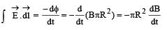 = -πR2B
∴ E × 2πR = – πR2B

(b) is the correct option.
Two identical circular loops of metal wire are lying on a table without touching each other. Loop-A carries a current which increases with time. In response, the loop-B- a)remains stationary
- b)is attracted by the loop-A
- c)is repelled by the loop-A
- d)rotates about its CM, with CM fixed
Correct answer is option 'C'. Can you explain this answer?
Two identical circular loops of metal wire are lying on a table without touching each other. Loop-A carries a current which increases with time. In response, the loop-B
a)
remains stationary
b)
is attracted by the loop-A
c)
is repelled by the loop-A
d)
rotates about its CM, with CM fixed
|
|
Sakshi Shah answered |
Explanation:
Introduction:
When a current-carrying loop is placed in the vicinity of another loop, the magnetic field produced by the first loop interacts with the magnetic field of the second loop. This interaction can result in either attraction or repulsion between the loops, depending on the orientation and direction of the currents.
Scenario:
In this scenario, we have two identical circular loops of metal wire, labeled as Loop-A and Loop-B. Loop-A carries a current that is increasing with time.
Effect on Loop-B:
The current in Loop-A produces a magnetic field around it. According to Ampere's law, the magnetic field lines due to a current-carrying loop are in the form of concentric circles around the loop. The direction of the magnetic field can be determined using the right-hand rule.
Magnetic Field Direction:
To determine the magnetic field direction at the location of Loop-B, imagine holding the Loop-A with your right hand such that your thumb points in the direction of the current. The curled fingers will give you the direction of the magnetic field lines.
Loop-B Alignment:
If Loop-B is placed such that the current in Loop-A and Loop-B are flowing in the same direction, the magnetic fields produced by the two loops will be in the same direction. According to the right-hand rule, like magnetic fields repel each other. Therefore, Loop-B will be repelled by Loop-A.
Loop-B Repulsion:
The repulsion between Loop-A and Loop-B is due to the interaction of their magnetic fields. The repulsive force between the two loops is a result of the magnetic forces acting on the moving charges in the wire.
Conclusion:
In conclusion, when a current-carrying loop is placed near another loop, the interaction between their magnetic fields can result in either attraction or repulsion. In this scenario, Loop-B is repelled by Loop-A because their currents are flowing in the same direction.
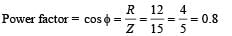
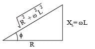
The power factor of an AC circuit having resistance (R) and inductance (L) connected in series and an angular velocity ω is- a)R/ ω L
- b)R/(R2 + ω2L2)1/2
- c)ω L/R
- d)R/(R2 – ω2L2)1/2
Correct answer is option 'B'. Can you explain this answer?
The power factor of an AC circuit having resistance (R) and inductance (L) connected in series and an angular velocity ω is
a)
R/ ω L
b)
R/(R2 + ω2L2)1/2
c)
ω L/R
d)
R/(R2 – ω2L2)1/2

|
Nabanita Basu answered |
(b) The impedance triangle for resistance (R) and inductor
(L) connected in series is shown in the figure.


A coil of inductance 300 mH and resistance 2 W is connected to a source of voltage 2 Ω The current reaches half of its steady state value in- a)0.1 s
- b)0.05 s
- c)0.3 s
- d)0.15 s
Correct answer is option 'A'. Can you explain this answer?
A coil of inductance 300 mH and resistance 2 W is connected to a source of voltage 2 Ω The current reaches half of its steady state value in
a)
0.1 s
b)
0.05 s
c)
0.3 s
d)
0.15 s
|
|
Aryan Iyer answered |
Understanding the RL Circuit
An RL circuit consists of a resistor (R) and an inductor (L) connected in series with a voltage source (V). The time-dependent behavior of the current (I) in such a circuit is governed by the first-order differential equation derived from Kirchhoff’s laws.
Key Parameters
- Inductance (L): 300 mH = 0.3 H
- Resistance (R): 2 Ω
- Voltage (V): 2 V
Steady-State Current Calculation
The steady-state current (I₀) can be calculated using Ohm’s Law:
- I₀ = V / R = 2 V / 2 Ω = 1 A
Time Constant for the RL Circuit
The time constant (τ) for an RL circuit is given by:
- τ = L / R = 0.3 H / 2 Ω = 0.15 s
Current Growth Equation
The current in the RL circuit rises according to the following equation:
- I(t) = I₀(1 - e^(-t/τ))
Where e is the base of the natural logarithm.
Finding Half of Steady-State Current
To find the time (t) when the current reaches half of its steady-state value (0.5 A):
1. Set I(t) = 0.5 A:
- 0.5 A = 1 A(1 - e^(-t/0.15))
2. Simplifying the equation:
- 0.5 = 1 - e^(-t/0.15)
- e^(-t/0.15) = 0.5
3. Solving for t:
- -t/0.15 = ln(0.5)
- t = -0.15 * ln(0.5) ≈ 0.1 s
Conclusion
Thus, the time required for the current to reach half of its steady-state value is approximately 0.1 seconds, confirming that option 'A' is correct.
A boat is moving due east in a region where the earth's magnetic field is 5.0 × 10⁻⁵ NA–1 m–1 due north and horizontal.
The boat carries a vertical aerial 2 m long. If the speed of the boat is 1.50 ms–1, the magnitude of the induced emf in the wire of aerial is:- a)0.75 mV
- b)0.50 mV
- c)0.15 mV
- d)1 mV
Correct answer is option 'C'. Can you explain this answer?
A boat is moving due east in a region where the earth's magnetic field is 5.0 × 10⁻⁵ NA–1 m–1 due north and horizontal.
The boat carries a vertical aerial 2 m long. If the speed of the boat is 1.50 ms–1, the magnitude of the induced emf in the wire of aerial is:
The boat carries a vertical aerial 2 m long. If the speed of the boat is 1.50 ms–1, the magnitude of the induced emf in the wire of aerial is:
a)
0.75 mV
b)
0.50 mV
c)
0.15 mV
d)
1 mV

|
Mira Roy answered |
Induced emf = vBH l = 1.5 × 5 × 10–5 × 2 = 15 × 10–5
= 0.15 mV
= 0.15 mV
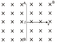
The figure shows certain wire segments joined together to form a coplanar loop. The loop is placed in a perpendicular magnetic field in the direction going into the plane of the figure. The magnitude of the field increases with time. I1 and I2 are the currents in the segments ab and cd. Then,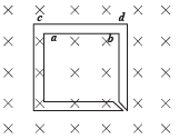
- a)I1 > I2
- b)I1 < I2
- c)I1 is in the direction ba and I2 is in the direction cd
- d)I1 is in the direction ab and I2 is in the direction dc
Correct answer is option 'D'. Can you explain this answer?
The figure shows certain wire segments joined together to form a coplanar loop. The loop is placed in a perpendicular magnetic field in the direction going into the plane of the figure. The magnitude of the field increases with time. I1 and I2 are the currents in the segments ab and cd. Then,
a)
I1 > I2
b)
I1 < I2
c)
I1 is in the direction ba and I2 is in the direction cd
d)
I1 is in the direction ab and I2 is in the direction dc

|
Atharva Pillai answered |
The magnetic field is increasing in the downward direction. Therefore, according to Lenz’s law the current I1 will flow in the direction ab and I2 in the direction dc.
A conducting square loop of side L and resistance R moves in its plane with a uniform velocity v perpendicular to one of its sides. A magnetic induction B, constant in time and space, pointing perpendicular and into the plane of the loop exists everywhere.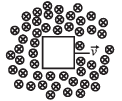 The current induced in the loop is:
- a)BLv/R clockwise
- b)BLv/R anticlockwise
- c)2BLv/R anticlockwise
- d)zero.
Correct answer is option 'D'. Can you explain this answer?
A conducting square loop of side L and resistance R moves in its plane with a uniform velocity v perpendicular to one of its sides. A magnetic induction B, constant in time and space, pointing perpendicular and into the plane of the loop exists everywhere.
The current induced in the loop is:
a)
BLv/R clockwise
b)
BLv/R anticlockwise
c)
2BLv/R anticlockwise
d)
zero.

|
Avantika Joshi answered |
NOTE : Since the rate of change of magnetic flux is zero, hence there will be no net induced emf and hence no current flowing in the loop.
Find out from amongst the four alternatives as to how the pattern would appear when the transparent sheet is folded at the dotted line.
- a)1
- b)2
- c)3
- d)4
Correct answer is option 'C'. Can you explain this answer?
Find out from amongst the four alternatives as to how the pattern would appear when the transparent sheet is folded at the dotted line.
a)
1
b)
2
c)
3
d)
4
|
|
Mayank Verma answered |
Bhai iska answer likhit m nhi mil sakta, paper fold karke practically dekh le
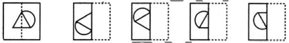
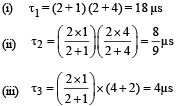
Find the time constant (in μs) for the given RC circuits in the given order respectively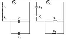
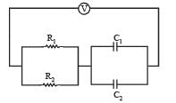 R1 = 1W, R2 = 2W, C1 = 4μF , C2 =2μF
- a)

- b)

- c)

- d)

Correct answer is option 'B'. Can you explain this answer?
Find the time constant (in μs) for the given RC circuits in the given order respectively
R1 = 1W, R2 = 2W, C1 = 4μF , C2 =2μF
a)
b)
c)
d)

|
Bhavya Joshi answered |
KEY CONCEPT :
Time constant of R – C circuit is τ = Req Ceq
An inductor (L = 100 mH), a resistor (R = 100 Ω) and a battery (E = 100 V) are initially connected in series as shown in the figure. After a long time the battery is disconnected after short circuiting the points A and B. The current in the circuit 1 ms after the short circuit is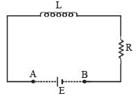
- a)1/eA
- b)eA
- c)0.1 A
- d)1 A
Correct answer is option 'A'. Can you explain this answer?
An inductor (L = 100 mH), a resistor (R = 100 Ω) and a battery (E = 100 V) are initially connected in series as shown in the figure. After a long time the battery is disconnected after short circuiting the points A and B. The current in the circuit 1 ms after the short circuit is
a)
1/eA
b)
eA
c)
0.1 A
d)
1 A

|
Swara Ahuja answered |
Ans.
Option
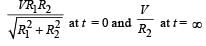
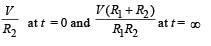
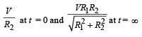
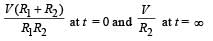
In the circuit shown below, the key K is closed at t = 0. The current through the battery is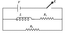
- a)
- b)
- c)
- d)
Correct answer is option 'C'. Can you explain this answer?
In the circuit shown below, the key K is closed at t = 0. The current through the battery is
a)
b)
c)
d)

|
Ipsita Sen answered |
At t = 0, no current will flow through L and R1
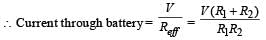
∴ Current through battery 
At t = ∞,
effective resistance, 
Alternating current can not be measured by D.C. ammeter because- a)Average value of current for complete cycle is zero
- b)A.C. Changes direction
- c)A.C. can not pass through D.C. Ammeter
- d)D.C. Ammeter will get damaged.
Correct answer is option 'A'. Can you explain this answer?
Alternating current can not be measured by D.C. ammeter because
a)
Average value of current for complete cycle is zero
b)
A.C. Changes direction
c)
A.C. can not pass through D.C. Ammeter
d)
D.C. Ammeter will get damaged.

|
Pragati Dey answered |
D.C. ammeter measure average current in AC current, average current is zero for complete cycle. Hence reading will be zero.
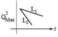
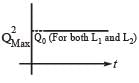
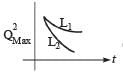
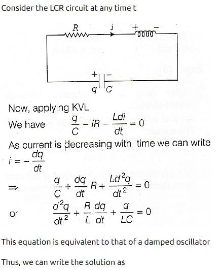
An LCR circuit is equivalent to a damped pendulum. In an LCR circuit the capacitor is charged to Q0 and then connected to the L and R as shown below :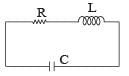 If a student plots graphs of the square of maximum charge
  on the capacitor with time(t) for two different values L1 and L2 (L1 > L,) of L then which of the following represents this graph correctly ? (plots are schematic and not drawn to scale)
- a)
- b)
- c)
- d)
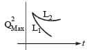
Correct answer is option 'C'. Can you explain this answer?
An LCR circuit is equivalent to a damped pendulum. In an LCR circuit the capacitor is charged to Q0 and then connected to the L and R as shown below :
If a student plots graphs of the square of maximum charge on the capacitor with time(t) for two different values L1 and L2 (L1 > L,) of L then which of the following represents this graph correctly ? (plots are schematic and not drawn to scale)
on the capacitor with time(t) for two different values L1 and L2 (L1 > L,) of L then which of the following represents this graph correctly ? (plots are schematic and not drawn to scale)a)
b)
c)
d)

|
Pranavi Iyer answered |
Ans.
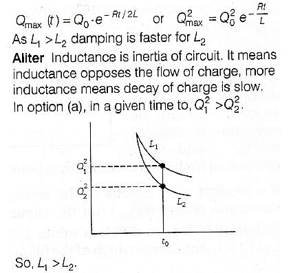
Option : (c)
A coil having n turns and resistance RΩ is connected with a galvanometer of resistance 4RΩ. This combination is moved in time t seconds from a magnetic field W1 weber to W2 weber. The induced current in the circuit is- a)

- b)

- c)

- d)

Correct answer is option 'B'. Can you explain this answer?
A coil having n turns and resistance RΩ is connected with a galvanometer of resistance 4RΩ. This combination is moved in time t seconds from a magnetic field W1 weber to W2 weber. The induced current in the circuit is
a)
b)
c)
d)

|
Subhankar Mukherjee answered |
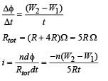
(∴ W2 &W1 are magnetic flux)
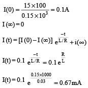
An inductor (L = 0.03 H) and a resistor (R = 0.15 kΩ) are connected in series to a battery of 15V EMF in a circuit shown below. The key K1 has been kept closed for a long time. Then at t = 0, K1 is opened and key K2 is closed simultaneously. At t = l ms, the current in the circuit will be : 
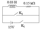
- a)6.7 mA
- b)0.67 mA
- c)100 mA
- d)67 mA
Correct answer is option 'B'. Can you explain this answer?
An inductor (L = 0.03 H) and a resistor (R = 0.15 kΩ) are connected in series to a battery of 15V EMF in a circuit shown below. The key K1 has been kept closed for a long time. Then at t = 0, K1 is opened and key K2 is closed simultaneously. At t = l ms, the current in the circuit will be :
a)
6.7 mA
b)
0.67 mA
c)
100 mA
d)
67 mA
|
|
Krish Ghoshal answered |
A fully charged capacitor C with initial charge q0 is connected to a coil of self inductance L at t = 0. The time at which the energy is stored equally between the electric and the magnetic fields is:- a)

- b)

- c)

- d)

Correct answer is option 'A'. Can you explain this answer?
A fully charged capacitor C with initial charge q0 is connected to a coil of self inductance L at t = 0. The time at which the energy is stored equally between the electric and the magnetic fields is:
a)
b)
c)
d)

|
Pankaj Sengupta answered |
Ans.
Option (a)

As initially, charge is maximum
∴ q = qocos ωt
Current,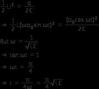
∴ q = qocos ωt
Current,
As initially, charge is maximum
∴ q = qocos ωt
Current,
∴ q = qocos ωt
Current,
In an LCR circuit as shown below both switches are open initially. Now switch S1 is closed, S2 kept open. (q is charge on the capacitor and τ = RC is Capacitive time constant).
Which of the following statement is correct ?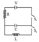
- a)Work done by the battery is half of the energy dissipated in the resistor
- b)At t = τ, q = CV/2
- c)At t = 2τ, q = CV (1 – e–2)
- d)At t = 2τ, q = CV (1 – e–1)
Correct answer is option 'C'. Can you explain this answer?
In an LCR circuit as shown below both switches are open initially. Now switch S1 is closed, S2 kept open. (q is charge on the capacitor and τ = RC is Capacitive time constant).
Which of the following statement is correct ?
Which of the following statement is correct ?
a)
Work done by the battery is half of the energy dissipated in the resistor
b)
At t = τ, q = CV/2
c)
At t = 2τ, q = CV (1 – e–2)
d)
At t = 2τ, q = CV (1 – e–1)
|
|
Ujwal Chawla answered |
Charge on he capacitor at any time t is given by
q = CV (1– et/τ)
at t = 2τ
q = CV (1 – e–2)
As shown in the figure, P and Q are two coaxial conducting loops separated by some distance. When the switch S is closed, a clockwise current IP flows in P (as seen by E) and an induced current IQ1 flows in Q. The switch remains closed for a long time. When S is opened, a current IQ2 flows in Q.
Then the direction IQ1 and IQ2 (as seen by E) are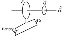
- a)respectively clockwise and anti-clockwise
- b)both clockwise
- c)both anti-clockwise
- d)respectively anti-clockwise and clockwise
Correct answer is option 'D'. Can you explain this answer?
As shown in the figure, P and Q are two coaxial conducting loops separated by some distance. When the switch S is closed, a clockwise current IP flows in P (as seen by E) and an induced current IQ1 flows in Q. The switch remains closed for a long time. When S is opened, a current IQ2 flows in Q.
Then the direction IQ1 and IQ2 (as seen by E) are
Then the direction IQ1 and IQ2 (as seen by E) are
a)
respectively clockwise and anti-clockwise
b)
both clockwise
c)
both anti-clockwise
d)
respectively anti-clockwise and clockwise

|
Rithika Mishra answered |
When switch S is closed, a magnetic field is set-up in the space around P. The field lines threading Q increases in the direction from right to left. According to Lenz's law, IQ1 will flow so as to oppose the cause and flow in anticlockwise direction as seen by E.
Reverse is the case when S is opened. IQ2 will be clockwise.
Reverse is the case when S is opened. IQ2 will be clockwise.
A metal rod moves at a constant velocity in a direction perpendicular to its length. A constant, uniform magnetic field exists in space in a direction perpendicular to the rod as well as its velocity. Select the correct statement(s) from the following- a)The entire rod is at the same electric potential.
- b)There is an electric field in the rod.
- c)The electric potential is highest at the centre of the rod and decreases towards its ends.
- d)The electric potential is lowest at the centre of the rod, and increases towards its ends
Correct answer is option 'B'. Can you explain this answer?
A metal rod moves at a constant velocity in a direction perpendicular to its length. A constant, uniform magnetic field exists in space in a direction perpendicular to the rod as well as its velocity. Select the correct statement(s) from the following
a)
The entire rod is at the same electric potential.
b)
There is an electric field in the rod.
c)
The electric potential is highest at the centre of the rod and decreases towards its ends.
d)
The electric potential is lowest at the centre of the rod, and increases towards its ends
|
|
Avantika Joshi answered |
A motional emf, e = Blv is induced in the rod. Or we can say a potential difference is induced between the two ends of the rod AB, with A at higher potential and B at lower potential.
Due to this potential difference, there is an electric field in the rod.
Due to this potential difference, there is an electric field in the rod.
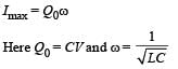
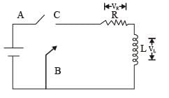
In the given circuit the capacitor (C) may be charged through resistance R by a battery V by closing switch S1. Also when S1 is opened and S2 is closed the capacitor is connected in series with inductor (L).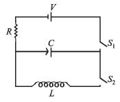 Q. When the capacitor gets charged completely, S1 is opened and S2 is closed. Then,
- a)at t = 0, energy stored in the circuit is purely in the form of magnetic energy
- b)at any time t > 0, current in the circuit is in the same direction
- c)at t > 0, there is no exchange of energy between the inductor and capacitor
- d)at any time t > 0, instantaneous current in the circuit may be

Correct answer is option 'D'. Can you explain this answer?
In the given circuit the capacitor (C) may be charged through resistance R by a battery V by closing switch S1. Also when S1 is opened and S2 is closed the capacitor is connected in series with inductor (L).
Q. When the capacitor gets charged completely, S1 is opened and S2 is closed. Then,
a)
at t = 0, energy stored in the circuit is purely in the form of magnetic energy
b)
at any time t > 0, current in the circuit is in the same direction
c)
at t > 0, there is no exchange of energy between the inductor and capacitor
d)
at any time t > 0, instantaneous current in the circuit may be
|
|
Niharika Deshpande answered |
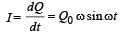
The instantaneous charge on plates at any time t during discharging is
Q = Q0 cos ωt
∴ Instantaneous current,
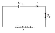
∴ The magnitude of maximum current
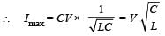
A metal conductor of length 1 m rotates vertically about one of its ends at angular velocity 5 radians per second. If the horizontal component of earth’s magnetic field is 0.2×10⁻⁴T, then the e.m.f. developed between the two ends of the conductor is- a)5 mV
- b)50 μV
- c)5 μV
- d)50 mV
Correct answer is option 'B'. Can you explain this answer?
A metal conductor of length 1 m rotates vertically about one of its ends at angular velocity 5 radians per second. If the horizontal component of earth’s magnetic field is 0.2×10⁻⁴T, then the e.m.f. developed between the two ends of the conductor is
a)
5 mV
b)
50 μV
c)
5 μV
d)
50 mV

|
Dipika Choudhury answered |
Two coaxial solenoids of different radius carry current I in the same direction.  be the magnetic force on the inner solenoid due to the outer one and
  be the magnetic force on the outer solenoid due to the inner one. Then :
- a)
 is radially inwards and
  = 0
= 0 - b)
 is radially outwards and
  = 0
= 0 - c)

 = 0
= 0 - d)
 is radially inwards and
  is radially outwards
Correct answer is option 'C'. Can you explain this answer?
Two coaxial solenoids of different radius carry current I in the same direction. be the magnetic force on the inner solenoid due to the outer one and be the magnetic force on the outer solenoid due to the inner one. Then :
be the magnetic force on the inner solenoid due to the outer one and be the magnetic force on the outer solenoid due to the inner one. Then :a)
is radially inwards and = 0b)
is radially outwards and = 0c)
= 0d)
is radially inwards and is radially outwards

|
Akshita Nair answered |

because of action and reaction pair
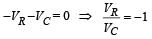
In the circuit shown here, the point ‘C’ is kept connected to point ‘A’ till the current flowing through the circuit becomes constant. Afterward, suddenly, point ‘C’ is disconnected from point ‘A’ and connected to point ‘B’ at time t = 0. Ratio of the voltage across resistance and the inductor at t = L/R will be equal to: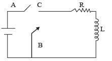
- a)

- b)1
- c)-1
- d)

Correct answer is option 'C'. Can you explain this answer?
In the circuit shown here, the point ‘C’ is kept connected to point ‘A’ till the current flowing through the circuit becomes constant. Afterward, suddenly, point ‘C’ is disconnected from point ‘A’ and connected to point ‘B’ at time t = 0. Ratio of the voltage across resistance and the inductor at t = L/R will be equal to:
a)
b)
1
c)
-1
d)

|
Mehul Chavan answered |
Applying Kirchhoff's law of voltage in closed loop
A point charge Q is moving in a circular orbit of radius R in the x-y plane with an angular velocity w. This can be considered as equivalent to a loop carrying a steady current  A uniform magnetic field along the positive z-axis is now switched on, which increases at a constant rate from 0 to B in one second. Assume that the radius of the orbit remains constant. The application of the magnetic field induces an emf in the orbit. The induced emf is defined as the work done by an induced electric field in moving a unit positive charge around a closed loop. It is known that, for an orbiting charge, the magnetic dipole moment is proportional to the angular momentum with a proportionality constant γ.Q. The change in the magnetic dipole moment associated with the orbit, at the end of the time interval of the magnetic field change, is
- a)–γBQR2
- b)

- c)

- d)γBQR2
Correct answer is option 'B'. Can you explain this answer?
A point charge Q is moving in a circular orbit of radius R in the x-y plane with an angular velocity w. This can be considered as equivalent to a loop carrying a steady current A uniform magnetic field along the positive z-axis is now switched on, which increases at a constant rate from 0 to B in one second. Assume that the radius of the orbit remains constant. The application of the magnetic field induces an emf in the orbit. The induced emf is defined as the work done by an induced electric field in moving a unit positive charge around a closed loop. It is known that, for an orbiting charge, the magnetic dipole moment is proportional to the angular momentum with a proportionality constant γ.
A uniform magnetic field along the positive z-axis is now switched on, which increases at a constant rate from 0 to B in one second. Assume that the radius of the orbit remains constant. The application of the magnetic field induces an emf in the orbit. The induced emf is defined as the work done by an induced electric field in moving a unit positive charge around a closed loop. It is known that, for an orbiting charge, the magnetic dipole moment is proportional to the angular momentum with a proportionality constant γ.Q. The change in the magnetic dipole moment associated with the orbit, at the end of the time interval of the magnetic field change, is
a)
–γBQR2
b)
c)
d)
γBQR2

|
Bhavana Dey answered |
Given M = γ L
∴ M = γ mωR2
∴ M = γ m (Δω) R2 ...(1)
∴ M = γ mωR2
∴ M = γ m (Δω) R2 ...(1)
 ...(2)
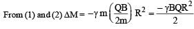
The negative sign shows that change is opposite to the direction of B. (b) is the correct option.
Chapter doubts & questions for Electromagnetic Induction and Alternating Current - 35 Years Chapter wise Previous Year Solved Papers for JEE 2025 is part of JEE exam preparation. The chapters have been prepared according to the JEE exam syllabus. The Chapter doubts & questions, notes, tests & MCQs are made for JEE 2025 Exam. Find important definitions, questions, notes, meanings, examples, exercises, MCQs and online tests here.
Chapter doubts & questions of Electromagnetic Induction and Alternating Current - 35 Years Chapter wise Previous Year Solved Papers for JEE in English & Hindi are available as part of JEE exam.
Download more important topics, notes, lectures and mock test series for JEE Exam by signing up for free.
35 Years Chapter wise Previous Year Solved Papers for JEE
347 docs|185 tests
|
|
© EduRev
|
Education Revolution
|


|


Signup to see your scores
go up
within 7 days!
within 7 days!
Takes less than 10 seconds to signup