


All Exams >
Mechanical Engineering >
GATE Mechanical (ME) Mock Test Series 2026 >
All Questions
All questions of Theory of Machines (TOM) for Mechanical Engineering Exam
Consider the following statements1. A round bar in a round hole form a turning pair.
2. A square bar in a square hole forms a sliding pair.
3. A vertical shaft in a footstep bearing forms a successful constraint.
Of these statements[IES-2000] - a)1 and 2 are correct
- b)1 and 3 are correct
- c)2 and 3 are correct
- d)1, 2 and 3 are correct
Correct answer is option 'C'. Can you explain this answer?
Consider the following statements
1. A round bar in a round hole form a turning pair.
2. A square bar in a square hole forms a sliding pair.
3. A vertical shaft in a footstep bearing forms a successful constraint.
Of these statements
2. A square bar in a square hole forms a sliding pair.
3. A vertical shaft in a footstep bearing forms a successful constraint.
Of these statements
[IES-2000]
a)
1 and 2 are correct
b)
1 and 3 are correct
c)
2 and 3 are correct
d)
1, 2 and 3 are correct
|
|
Varun Khanna answered |
If round bar is placed in a round hole it will have both turning and as well as sliding pair also.

A planar mechanism has 8 links and 10 rotary joints. The number of degrees of freedom of the mechanism, using Grubler's criterion, is - a)0
- b)1
- c)2
- d)3
Correct answer is option 'B'. Can you explain this answer?
A planar mechanism has 8 links and 10 rotary joints. The number of degrees of freedom of the mechanism, using Grubler's criterion, is
a)
0
b)
1
c)
2
d)
3
|
|
Amar Gupta answered |
Whatever may be the number of links and joints Grubler's criterion applies to mechanism with only single degree freedom. Subject to the condition 3l-2j-4=0 and it satisfy this condition.
Degree of freedom is given by
Degree of freedom is given by
Instantaneous center of a body rolling with sliding on a stationary curved surface lies
a)at the point of contactb)on the common normal at the point of contactc)on the common tangent at the point of contactd)at the centre of curvature of the stationary surfaceCorrect answer is option 'B'. Can you explain this answer?

|
Vivek Sharma answered |
Answer will be A only if sliding is not there and body is purely rolling but in this case answer should be B as sliding occurs.
Beam engine mechanism is an example of - a) double crank mechanism
- b) double lever mechanism
- c) crank and lever mechanism
- d) none of the above
Correct answer is option 'C'. Can you explain this answer?
Beam engine mechanism is an example of
a)
double crank mechanism
b)
double lever mechanism
c)
crank and lever mechanism
d)
none of the above

|
Sagarika Patel answered |
The different types of four bar inversions are as follows:
1) Double crank mechanism: This is the second inversion of four bar chain. It is used for transmitting rotary motion from one crank to the other crank. Coupled wheels of locomotive is an example of this inversion.
2) Crank and lever mechanism: This is the first inversion of four bar chain. It is used to convert rotary motion of input link into oscillatory motion of output link. Beam engine mechanism is an example of this inversion and it consists of four links. The crank rotates about a fixed centre and the lever oscillates at another fixed centre.
3) Double lever mechanism: This is the third inversion of four bar chain. It is used for transmitting oscillatory motion from one lever to another. Ackermann steering gear mechanism is an example of double lever mechanism.
In a four-bar linkage, S denotes the shortest link length, L is the longest link length, P and Q are the lengths of other two links. At least one of the three moving links will rotate by 360° if- a)S + L ≤ P + Q
- b)S + L > P + Q
- c)S + P ≤ L + Q
- d)S + P > L + Q
Correct answer is option 'A'. Can you explain this answer?
In a four-bar linkage, S denotes the shortest link length, L is the longest link length, P and Q are the lengths of other two links. At least one of the three moving links will rotate by 360° if
a)
S + L ≤ P + Q
b)
S + L > P + Q
c)
S + P ≤ L + Q
d)
S + P > L + Q
|
|
Shanaya Chopra answered |
According to Grashoff’s Law for a four bar mechanism, the sum of shortest and longest link lengths should not be greater than the sum of the remaining two link length.
i.e. S + L ≤ P + Q
Can you explain the answer of this question below:The minimum number of links in a single degree-of-freedom planar mechanism with both higher and lower kinematic pairs is:A: 2B: 3C: 4D: 5The answer is b.

|
Rahul Chatterjee answered |
From the Kutzbach criterion the degree of freedom,
n = 3(l − 1) − 2j − h
For single degree of Freedom (n = 1),
1 = 3(l − 1) − 2j − h
3l − 2j − 4 − h = 0 …(i)
The simplest possible mechanisms of single degree of freedom is four-bar mechanism. For this mechanism j = 4, h = 0
From equation (i), we have
3l − 2 x 4 − 4 − 0 = 0
or, l = 4.
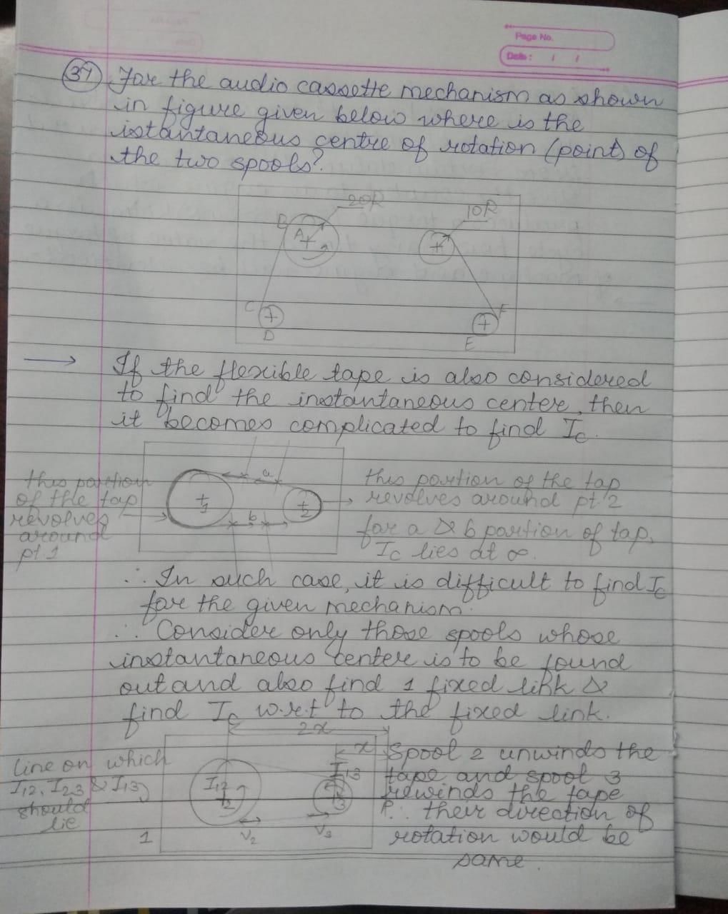
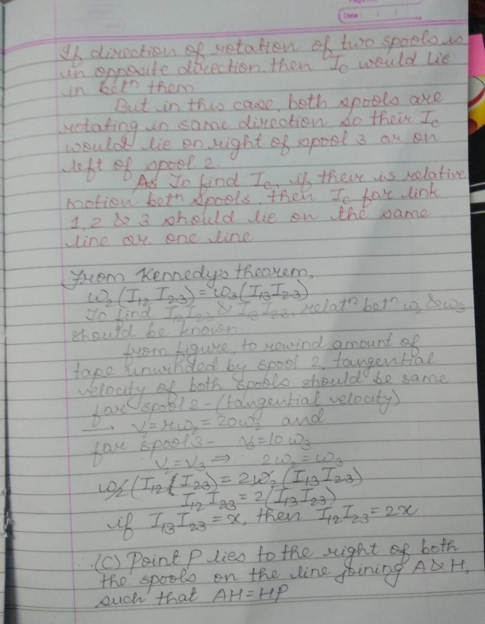
For the audio cassette mechanism shown in Figure given below where is the instantaneous centre of rotation (point) of the two spools? 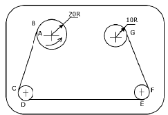 [GATE-1999]
- a)Point P lies to the left of both the spools but at infinity along the line joining A and H
- b)Point P lies in between the two spools on the line joining A and H, such that PH = 2 AP
- c)Point P lies to the right of both the spools on the line joining A and H, such that AH = HP
- d)Point P lies at the intersection of the line joining B and C and the line joining G and F
Correct answer is option 'D'. Can you explain this answer?
For the audio cassette mechanism shown in Figure given below where is the instantaneous centre of rotation (point) of the two spools?
[GATE-1999]
a)
Point P lies to the left of both the spools but at infinity along the line joining A and H
b)
Point P lies in between the two spools on the line joining A and H, such that PH = 2 AP
c)
Point P lies to the right of both the spools on the line joining A and H, such that AH = HP
d)
Point P lies at the intersection of the line joining B and C and the line joining G and F
|
|
Pooja Shende answered |
Which of the following statements is incorrect - a)Grashof's rule states that for a planar crank-rocker four bar mechanism, the sum of the shortest and longest link lengths cannot be less than the sum of the remaining two link lengths.
- b)Inversions of a mechanism are created-by fixing different links one at a time.
- c)Geneva mechanism is an intermittent motion device.
- d)Gruebler's criterion assumes mobility of a planar mechanism to be one.
Correct answer is option 'A'. Can you explain this answer?
Which of the following statements is incorrect
a)
Grashof's rule states that for a planar crank-rocker four bar mechanism, the sum of the shortest and longest link lengths cannot be less than the sum of the remaining two link lengths.
b)
Inversions of a mechanism are created-by fixing different links one at a time.
c)
Geneva mechanism is an intermittent motion device.
d)
Gruebler's criterion assumes mobility of a planar mechanism to be one.
|
|
Rajeev Sharma answered |
Correct for a) Grashof’s rule states that the sum of the shortest and longest link for a planar Crank-rocker four bar mechanism can not be greater than the sum of the remaining two link lengths.

Which one of the following engines will have heavier flywheel than the remaining ones?- a)40 H.P. four-stroke petrol engine running at 1500 rpm.
- b)40 H.P. two-stroke petrol engine running at 1500 rpm.
- c)40 H.P. two-stroke diesel engine running at 750 rpm.
- d)40 H.P. four-stroke diesel engine running at 750 rpm.
Correct answer is option 'D'. Can you explain this answer?
Which one of the following engines will have heavier flywheel than the remaining ones?
a)
40 H.P. four-stroke petrol engine running at 1500 rpm.
b)
40 H.P. two-stroke petrol engine running at 1500 rpm.
c)
40 H.P. two-stroke diesel engine running at 750 rpm.
d)
40 H.P. four-stroke diesel engine running at 750 rpm.
|
|
Nandini Banerjee answered |
The four stroke engine running at lower speed needs heavier fly wheel.
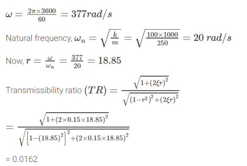
A machine of 250 kg mass is supported on springs of total stiffness 100 kN/m. Machine has an unbalanced rotating force of 350 N at speed of 3600 rpm. Assuming a damping factor of 0.15, the value of transmissibility ratio is - a)0.0531
- b)0.9922
- c)0.0162
- d)0.0028
Correct answer is option 'C'. Can you explain this answer?
A machine of 250 kg mass is supported on springs of total stiffness 100 kN/m. Machine has an unbalanced rotating force of 350 N at speed of 3600 rpm. Assuming a damping factor of 0.15, the value of transmissibility ratio is
a)
0.0531
b)
0.9922
c)
0.0162
d)
0.0028

|
Swara Dasgupta answered |
The minimum number of links in a single degree-of-freedom planar mechanism with both higher and lower kinematic pairs is - a)2
- b)3
- c)4
- d)5
Correct answer is 'C'. Can you explain this answer?
The minimum number of links in a single degree-of-freedom planar mechanism with both higher and lower kinematic pairs is
a)
2
b)
3
c)
4
d)
5
|
|
Rajeev Sharma answered |
From the Kutzbach criterion the degree of freedom,
n = 3(l − 1) − 2j − h
For single degree of Freedom (n = 1),
1 = 3(l − 1) − 2j − h
3l − 2j − 4 − h = 0 …(i)
The simplest possible mechanisms of single degree of freedom is four-bar mechanism. For this mechanism j = 4, h = 0
From equation (i), we have
3l − 2 x 4 − 4 − 0 = 0
or, l = 4.
The figure below shows a planar mechanism with single degree of freedom. The instant centre 24 for the given configuration is located at a position[GATE-2004]a)L b)Mc)N d)∞Correct answer is option 'D'. Can you explain this answer?
|
|
Sagarika Patel answered |
The Correct nswer is d.
Given planar mechanism has degree of freedom, N = 1 and two infinite parallel lines meet at infinity. So, the instantaneous centre I24 will be at N , but for single degree of freedom, system moves only in one direction.
Hence, I24 is located at infinity(∞)
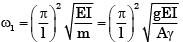
A uniform rigid rod of mass m = 1 kg and length L = 1 m is hinged at its centre and laterally supported at one end by a spring of constant k = 300 N/m. The natural frequency (ωn in rad/s is- a)10
- b)20
- c)30
- d)40
Correct answer is option 'A'. Can you explain this answer?
A uniform rigid rod of mass m = 1 kg and length L = 1 m is hinged at its centre and laterally supported at one end by a spring of constant k = 300 N/m. The natural frequency (ωn in rad/s is
a)
10
b)
20
c)
30
d)
40
|
|
Milan Goyal answered |
A uniform rigid rod of mass m = 1 kg and length L = 1 m is hinged at its centre & laterally supported at one end by a spring of spring constant k = 300N/m. The natural frequency ωn in rad/s is 10
Match the following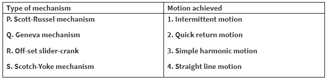
- a)P-2 Q-3 R-1 S-4
- b)P-3 Q-2 R-4 S-1
- c)P-4 Q-1 R-2 S-3
- d)P-4 Q-3 R-1 S-2
Correct answer is 'C'. Can you explain this answer?
Match the following
a)
P-2 Q-3 R-1 S-4
b)
P-3 Q-2 R-4 S-1
c)
P-4 Q-1 R-2 S-3
d)
P-4 Q-3 R-1 S-2

|
Shubham Chik answered |
For q it is 1 because the geneva mechanism is used in ship so continuous motion is not there so there they prefer mechanism which can be stop or start at any moment
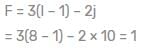
A linkage is shown below in the figure in which links ABC and DEF are ternary Jinks whereas AF, BE and CD are binary links.
The degrees of freedom of the linkage when link ABC is fixed are
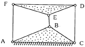 [IES-2002]
- a)0
- b)1
- c)2
- d)3
Correct answer is option 'A'. Can you explain this answer?
A linkage is shown below in the figure in which links ABC and DEF are ternary Jinks whereas AF, BE and CD are binary links.
The degrees of freedom of the linkage when link ABC is fixed are
[IES-2002]
a)
0
b)
1
c)
2
d)
3

|
Telecom Tuners answered |
To calculate the degrees of freedom (DOF) of the given linkage, we can use Gruebler's equation for planar mechanisms:
F=3(n−1)−2j−h
Where:
- F is the degrees of freedom.
- n is the number of links in the mechanism.
- j is the number of lower pairs (revolute or prismatic joints).
- h is the number of higher pairs (if any, typically ignored in simple linkages).
Step 1: Count the number of links (nnn)
In the figure:
- Links ABC and DEF are ternary links (each connects three joints), so we count each as one link.
- Links AF, BE, and CD are binary links (each connects two joints).
Thus, the total number of links nnn is:
n=2(ternary links)+3(binary links)=5
Step 2: Count the number of joints (j)
In the figure:
- There are six revolute joints, one at each intersection of the links: A, F, B, E, C, and D.
Thus, the total number of lower pairs (joints) j is:
j=6
Step 3: Apply Gruebler’s equation
Substitute the values into Gruebler’s equation:
F=3(n−1)−2j
F=3(5−1)−2(6)
F=3(4)−12
F=12−12=0
Conclusion:
The degrees of freedom of the linkage is F=0, meaning the linkage is a structure and does not have any mobility when the link ABC is fixed.
Thus, the correct answer is:
Option 1: 0.
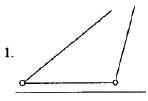
The kinematic chain shown in the above figure is a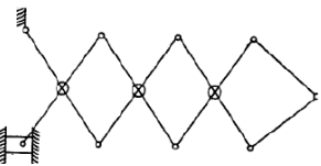 [IES-2000]
- a)structure
- b)mechanism with one degree of freedom
- c)mechanism with two degree of freedom
- d)mechanism with more than two degrees of freedom
Correct answer is option 'B'. Can you explain this answer?
The kinematic chain shown in the above figure is a
[IES-2000]
a)
structure
b)
mechanism with one degree of freedom
c)
mechanism with two degree of freedom
d)
mechanism with more than two degrees of freedom

|
Akhil Sharma answered |
 b is the correct option
______ is the study to know the displacement, velocity and acceleration of a part of the machine.- a)Kinematics
- b)Kinetics
- c)Statics
- d)All of the above
Correct answer is option 'A'. Can you explain this answer?
______ is the study to know the displacement, velocity and acceleration of a part of the machine.
a)
Kinematics
b)
Kinetics
c)
Statics
d)
All of the above
|
|
Neha Joshi answered |
Kinematics is the study to know the displacement, velocity and acceleration of a part of the machine.
The mechanism used in a shaping machine is - a)A closed 4-bar chain having 4 revolute pairs
- b)A closed 6-bar chain having 6 revolute pairs
- c)A closed 4-bar chain having 2 revolute and 2 sliding pairs
- d)An inversion of the single slider-crank chain
Correct answer is option 'D'. Can you explain this answer?
The mechanism used in a shaping machine is
a)
A closed 4-bar chain having 4 revolute pairs
b)
A closed 6-bar chain having 6 revolute pairs
c)
A closed 4-bar chain having 2 revolute and 2 sliding pairs
d)
An inversion of the single slider-crank chain
|
|
Sanya Agarwal answered |
Quick return mechanism.
The ratio of maximum fluctuation of speed to the mean speed is called- a) fluctuation of energy
- b) maximum fluctuation of energy
- c)coefficient of fluctuation of speed
- d)none of the mentioned
Correct answer is option 'C'. Can you explain this answer?
The ratio of maximum fluctuation of speed to the mean speed is called
a)
fluctuation of energy
b)
maximum fluctuation of energy
c)
coefficient of fluctuation of speed
d)
none of the mentioned

|
Anirban Khanna answered |
The co-efficient of fluctuation of speed is the ratio of maximum fluctuation of speed to the mean speed.
Match the following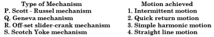
- a)P-2 Q-3 R-1 S-4
- b)P-3 Q-2 R-4 S-1
- c)P-4 Q-1 R-2 S-3
- d)P-4 Q-3 R-1 S-2
Correct answer is option 'C'. Can you explain this answer?
Match the following
a)
P-2 Q-3 R-1 S-4
b)
P-3 Q-2 R-4 S-1
c)
P-4 Q-1 R-2 S-3
d)
P-4 Q-3 R-1 S-2
|
|
Trilochan Thakur answered |
Geneva mechanism and ratchet mechanism is a intermittent motion machine mechanism.hence C
Which of the following conditions are to be satisfied by a two-mass system which is dynamically equivalent to a rigid body?1. The total mass should be equal to that of the rigid body.
2. The centre of gravity should coincide with that of the rigid body.
3. The total moment of inertia about an axis through the centre of gravity must be equal to that of the rigid body.Select the correct answer using the codes given below: - a)1 and 2
- b)2 and 3
- c)1 and 3
- d)None of the above
Correct answer is option 'C'. Can you explain this answer?
Which of the following conditions are to be satisfied by a two-mass system which is dynamically equivalent to a rigid body?
1. The total mass should be equal to that of the rigid body.
2. The centre of gravity should coincide with that of the rigid body.
3. The total moment of inertia about an axis through the centre of gravity must be equal to that of the rigid body.
2. The centre of gravity should coincide with that of the rigid body.
3. The total moment of inertia about an axis through the centre of gravity must be equal to that of the rigid body.
Select the correct answer using the codes given below:
a)
1 and 2
b)
2 and 3
c)
1 and 3
d)
None of the above
|
|
Shreya Kulkarni answered |
A is false. The centre of gravity of the two masses should coincide with that of the rigid body.
What are the minimum number of kinematic pairs required in a kinematic chain?- a) 2 kinematic pairs
- b) 3 kinematic pairs
- c) 4 kinematic pairs
- d) None of the above
Correct answer is option 'C'. Can you explain this answer?
What are the minimum number of kinematic pairs required in a kinematic chain?
a)
2 kinematic pairs
b)
3 kinematic pairs
c)
4 kinematic pairs
d)
None of the above
|
|
Neha Joshi answered |
- If there is all pairs are lower pair of a kinematic chain then 4 pairs required to make a chain.
- But, if there is atleast one higher pair involved then minimum 3 pairs required to make a kinematic chain. Cam and follower is example of a kinematic chain and it includes total 3pairs.
One higher pair = two lower pair.
A shaft has two heavy rotors mounted on it. The transverse natural frequencies, considering each of the rotor separately, are 100 Hz and 200 Hz respectively. The lowest critical speed is- a)5367 r.p.m.
- b)6000 r.p.m.
- c)9360 r.p.m.
- d)2000 r.p.m.
Correct answer is option 'A'. Can you explain this answer?
A shaft has two heavy rotors mounted on it. The transverse natural frequencies, considering each of the rotor separately, are 100 Hz and 200 Hz respectively. The lowest critical speed is
a)
5367 r.p.m.
b)
6000 r.p.m.
c)
9360 r.p.m.
d)
2000 r.p.m.
|
|
Aniket Saini answered |
Calculation of Lowest Critical Speed of Shaft with Two Rotors
Given data:
Transverse natural frequency of first rotor (f1) = 100 Hz
Transverse natural frequency of second rotor (f2) = 200 Hz
Step 1: Calculation of Critical Speed of Each Rotor
- Critical speed of the rotor is the speed at which the frequency of rotation coincides with the natural frequency of the rotor.
- The critical speed of each rotor can be calculated using the formula:
Critical speed (Nc) = (f * 60) / p
Where,
f = natural frequency of the rotor
p = number of poles of the motor
For the first rotor:
Nc1 = (100 * 60) / 2 = 3000 rpm
For the second rotor:
Nc2 = (200 * 60) / 2 = 6000 rpm
Step 2: Calculation of Lowest Critical Speed of Shaft
- The lowest critical speed of the shaft is the speed at which the natural frequencies of both rotors coincide.
- The natural frequencies of the rotors are in the ratio of 1:2, which means that at some speed, their frequencies will become equal.
- Let the lowest critical speed of the shaft be Nc.
Then, (f2 / f1) = (Nc / Nc1)^2
(Nc / Nc1)^2 = 2
Nc / Nc1 = √2
Nc = Nc1 * √2
Nc = 3000 * √2 = 5367 rpm (approx.)
Therefore, the lowest critical speed of the shaft with two rotors mounted on it is 5367 rpm. The correct answer is option (a).
When two shafts are neither parallel nor intersecting, power can be transmitted by using- a)A pair of spur gears
- b)a pair of helical gears
- c)An Oldham's coupling
- d)a pair of spiral gears
Correct answer is option 'D'. Can you explain this answer?
When two shafts are neither parallel nor intersecting, power can be transmitted by using
a)
A pair of spur gears
b)
a pair of helical gears
c)
An Oldham's coupling
d)
a pair of spiral gears
|
|
Rajeev Menon answered |
When helical gears are used to drive non-parallel and non-intersecting shafts, they are commonly called spiral gears. The exact nature of the action between such gears is not generally understood. On spiral gear drives, the unique condition exists that gear of the pair has two circular pitches and two pitch surfaces; one pitch surface is a cylinder while the other is a plane.
When the shafts are at right angles, each gear has one circular pitch in its plane of rotation and another circular pitch in the direction of its axis. The second circular pitch is called the axial pitch. Each gear of the pair has a pitch cylinder whose diameter is determined by its number of teeth and circular pitch in the plane of rotation, and a pitch plane whose travel is controlled by the axial pitch. The axial pitch of any such gear is constant at all diameters, while its circular pitch in the plane of rotation is the same as the axial pitch of the mating gear.
The minimum number of links in a single degree-of-freedom planar mechanism with both higher and lower kinematic pairs is - a)2
- b)3
- c)4
- d)5
Correct answer is option 'C'. Can you explain this answer?
The minimum number of links in a single degree-of-freedom planar mechanism with both higher and lower kinematic pairs is
a)
2
b)
3
c)
4
d)
5
|
|
Anirban Khanna answered |
From the Kutzbach criterion the degree of freedom,
n = 3(l − 1) − 2j − h
For single degree of Freedom (n = 1),
1 = 3(l − 1) − 2j − h
3l − 2j − 4 − h = 0 …(i)
The simplest possible mechanisms of single degree of freedom is four-bar mechanism. For this mechanism j = 4, h = 0
From equation (i), we have
3l − 2 x 4 − 4 − 0 = 0
or, l = 4.
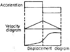
In a plate cam mechanism with reciprocating roller follower, the follower has a constant acceleration in the case of [GATE-1993]- a)cycloidal motion
- b)simple harmonic motion
- c)parabolic motion
- d)3-4-5 polynomial motion
Correct answer is option 'C'. Can you explain this answer?
In a plate cam mechanism with reciprocating roller follower, the follower has a constant acceleration in the case of
[GATE-1993]
a)
cycloidal motion
b)
simple harmonic motion
c)
parabolic motion
d)
3-4-5 polynomial motion

|
Tanvi Sarkar answered |
For uniform acceleration and retardation, the velocity of the follower must change at a constant rate and hence the velocity diagram of the follower consists of sloping straight lines. The velocity diagram represents everywhere the slope of the displacement diagram, the later must be a curve whose slope changes at a constant rate. Hence the displacement diagram consists of double parabola.
In vibration isolation system, if ω/ωn, then the phase difference between the transmitted force and the disturbing force is- a)0°
- b)90°
- c)180°
- d)270°
Correct answer is option 'C'. Can you explain this answer?
In vibration isolation system, if ω/ωn, then the phase difference between the transmitted force and the disturbing force is
a)
0°
b)
90°
c)
180°
d)
270°
|
|
Arshiya Dey answered |
In Vibration-isolation system, If the phase difference between transmitted force and the disturbing force is 180°C, then ω/ωn = 1.
In a 4-stroke I.C. engine, the turning moment during the compression stroke is- a)positive throughout
- b)negative throughout
- c)positive during major portion of the stroke
- d)negative during major portion of the stroke.
Correct answer is option 'A'. Can you explain this answer?
In a 4-stroke I.C. engine, the turning moment during the compression stroke is
a)
positive throughout
b)
negative throughout
c)
positive during major portion of the stroke
d)
negative during major portion of the stroke.
|
|
Aditya Chavan answered |
Explanation:
The 4-stroke internal combustion engine has four strokes, which are Intake stroke, Compression stroke, Power stroke, and Exhaust stroke. During the compression stroke, the piston moves from bottom dead center (BDC) to top dead center (TDC), compressing the air-fuel mixture in the combustion chamber. The turning moment during the compression stroke is the torque produced by the engine to rotate the crankshaft.
Positive Turning Moment:
The turning moment during the compression stroke is positive throughout. This means that the torque produced by the engine is in the same direction as the rotation of the crankshaft. The reason for the positive turning moment is that the air-fuel mixture in the combustion chamber is compressed, increasing the pressure and temperature. This increase in pressure and temperature causes the molecules of the air-fuel mixture to move faster and collide more frequently, producing a force that acts on the piston and rotates the crankshaft.
Negative Turning Moment:
If the turning moment during the compression stroke is negative, it means that the torque produced by the engine is opposite to the direction of rotation of the crankshaft. This is not possible in a 4-stroke internal combustion engine because the engine needs to compress the air-fuel mixture to ignite it during the power stroke. If the turning moment during the compression stroke is negative, it means that the engine is not compressing the air-fuel mixture, and the combustion will not take place during the power stroke.
Conclusion:
In conclusion, the turning moment during the compression stroke of a 4-stroke internal combustion engine is positive throughout. The positive turning moment is due to the compression of the air-fuel mixture, which increases the pressure and temperature, producing a force that acts on the piston and rotates the crankshaft.
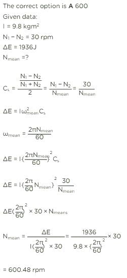
The speed of an engine varies from 210 rad/s to 190 rad/s. During the cycle the change in kinetic energy is found to be 400 Nm. The inertia of the flywheel in kg/m2 is- a)0.10
- b)0.20
- c)0.30
- d)0.40
Correct answer is 'A'. Can you explain this answer?
The speed of an engine varies from 210 rad/s to 190 rad/s. During the cycle the change in kinetic energy is found to be 400 Nm. The inertia of the flywheel in kg/m2 is
a)
0.10
b)
0.20
c)
0.30
d)
0.40
|
|
Amar Desai answered |
Given:
The speed of the engine varies from 210 rad/s to 190 rad/s.
The change in kinetic energy during the cycle is 400 Nm.
To find:
The inertia of the flywheel in kg/m2.
Solution:
The kinetic energy of a rotating object is given by the equation:
KE = (1/2) * I * ω2
where KE is the kinetic energy, I is the moment of inertia, and ω is the angular velocity.
We are given that the change in kinetic energy during the cycle is 400 Nm. This can be expressed as:
ΔKE = (1/2) * I * (ω2 - ω1)
where ω2 is the final angular velocity and ω1 is the initial angular velocity.
We are also given that the speed of the engine varies from 210 rad/s to 190 rad/s. This means that ω2 = 190 rad/s and ω1 = 210 rad/s.
Substituting these values in the equation, we have:
400 = (1/2) * I * (1902 - 2102)
Simplifying the equation further:
400 = (1/2) * I * (36100 - 44100)
400 = (1/2) * I * (-8000)
400 = -4000I
Dividing both sides of the equation by -4000, we get:
I = -400/4000
I = -0.1 kg/m2
Since moment of inertia cannot be negative, we take the absolute value of I:
I = 0.1 kg/m2
Therefore, the inertia of the flywheel is 0.1 kg/m2.
Hence, the correct answer is option 'A'.
In a multi-cylinder in-line internal combustion engine, even number of cylinders is chosen so that- a)uniform firing order is obtained
- b)the couples are balanced
- c)primary forces are balanced
- d)secondary forces are balanced
Correct answer is option 'D'. Can you explain this answer?
In a multi-cylinder in-line internal combustion engine, even number of cylinders is chosen so that
a)
uniform firing order is obtained
b)
the couples are balanced
c)
primary forces are balanced
d)
secondary forces are balanced
|
|
Yash Mukherjee answered |
The inertia forces reveals that for even number of cylinders (n > 2) i.e., for four, six, eight etc. cylinders the secondary forces are also completely balanced out.
Can you explain the answer of this question below:The number degrees of freedom of a planar linkage with 8 links and 9 simple revolute joints is
- A:
1
- B:
2
- C:
3
- D:
4
The answer is c.
The number degrees of freedom of a planar linkage with 8 links and 9 simple revolute joints is
1
2
3
4

|
Shivam Sharma answered |
Number of degree of freedom,
n = 3(l - 1) - 2J - h
= (3 x 7) - (2 x 9) - 0 = 3
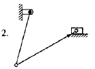
For the planar mechanism shown in figure select the most appropriate choice for the motion of link 2 when link 4 is moved upwards.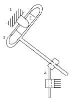
- a)Link 2 rotates clockwise
- b)Link 2 rotates counter – clockwise
- c)Link 2 does not move
- d)Link 2 motion cannot be determined
Correct answer is option 'B'. Can you explain this answer?
For the planar mechanism shown in figure select the most appropriate choice for the motion of link 2 when link 4 is moved upwards.
a)
Link 2 rotates clockwise
b)
Link 2 rotates counter – clockwise
c)
Link 2 does not move
d)
Link 2 motion cannot be determined
|
|
Ankit Kumar answered |
When link 4 is moved upwards, it will push link 3 upwards but since link 3&4 are joined by a revolute joint, the link will have to rotate in anticlockwise direction to move upwards. Since link 2&3 are joined, link 2 will show the same motion as link 3. So link will rotate in counter clockwise direction
The number of inversions for a slider crank mechanism is - a)6
- b)5
- c)4
- d)3
Correct answer is option 'C'. Can you explain this answer?
The number of inversions for a slider crank mechanism is
a)
6
b)
5
c)
4
d)
3
|
|
Shivam Sharma answered |
The four different mechanisms can be obtained by four different inversions of the chain. Slider Crank mechanism.
It has four binary links, three revolute pairs, one prismatic pair.By fixing links 1, 2, 3 in turn we get various inversions.
Consider the following statements:1. Flywheel and governor of an engine are the examples of an open loop control system
2. Governor is the example of closed loop control system
3. The thermostat of a refrigerator and relief valve of a boiler are the examples of closed loop control systemWhich of these statements is/are correct?- a)1 only
- b)2 and 3
- c)3 only
- d)2 only
Correct answer is option 'C'. Can you explain this answer?
Consider the following statements:
1. Flywheel and governor of an engine are the examples of an open loop control system
2. Governor is the example of closed loop control system
3. The thermostat of a refrigerator and relief valve of a boiler are the examples of closed loop control system
2. Governor is the example of closed loop control system
3. The thermostat of a refrigerator and relief valve of a boiler are the examples of closed loop control system
Which of these statements is/are correct?
a)
1 only
b)
2 and 3
c)
3 only
d)
2 only
|
|
Aditya Chavan answered |
Closed Loop and Open Loop Control Systems
Closed loop and open loop control systems are the two types of control systems used in engineering. A closed loop control system is a system in which the output is controlled by measuring the feedback and comparing it with the desired output. An open loop control system is a system in which the output is not controlled by feedback.
Examples
1. Flywheel and governor of an engine are the examples of an open loop control system
2. Governor is the example of closed loop control system
3. The thermostat of a refrigerator and relief valve of a boiler are the examples of closed loop control system
Explanation
Statement 1: Flywheel and governor of an engine are the examples of an open loop control system.
This statement is incorrect. The flywheel and governor of an engine are examples of closed loop control systems. The governor controls the engine speed by measuring the feedback from the engine and adjusting the fuel supply accordingly.
Statement 2: Governor is the example of closed loop control system.
This statement is correct. The governor is an example of a closed loop control system. The governor measures the feedback from the engine and adjusts the fuel supply to maintain the desired engine speed.
Statement 3: The thermostat of a refrigerator and relief valve of a boiler are the examples of closed loop control system.
This statement is correct. The thermostat of a refrigerator and relief valve of a boiler are examples of closed loop control systems. The thermostat measures the temperature inside the refrigerator and adjusts the cooling system to maintain the desired temperature. The relief valve of a boiler measures the pressure inside the boiler and adjusts the steam flow to maintain the desired pressure.
Conclusion
In summary, statement 1 is incorrect, statement 2 is correct, and statement 3 is correct. The governor, thermostat, and relief valve are all examples of closed loop control systems.
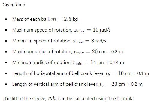
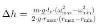
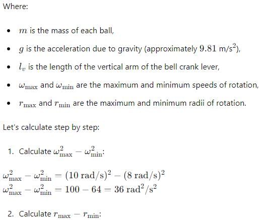
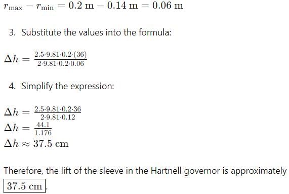
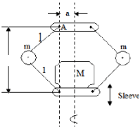
In a Hartnell governor, the mass of each ball is 2.5 kg. Maximum and minimum speeds of rotation are 10 rad/s and 8 rad/s respectively. Maximum and minimum radii of rotation are 20 cm and 14 cm respectively. The lengths of horizontal and vertical arms of bell crank levers are 10 cm and 20 cm respectively. Neglecting obliquity and gravitational effects, the lift of the sleeve is
- a)1.5 cm
- b)37.5 cm
- c)6.0 cm
- d)12.0 cm
Correct answer is option 'B'. Can you explain this answer?
In a Hartnell governor, the mass of each ball is 2.5 kg. Maximum and minimum speeds of rotation are 10 rad/s and 8 rad/s respectively. Maximum and minimum radii of rotation are 20 cm and 14 cm respectively. The lengths of horizontal and vertical arms of bell crank levers are 10 cm and 20 cm respectively. Neglecting obliquity and gravitational effects, the lift of the sleeve is
a)
1.5 cm
b)
37.5 cm
c)
6.0 cm
d)
12.0 cm

|
Gate Funda answered |
A Hartnell governor has its controlling force F given byF = p + qr
Where, is the radius of the balls and p and q are constants.
The governor becomes isochronous when- a)P = 0 and q is positive
- b)p is positive and q = 0
- c)p is negative and q is positive
- d)P is positive and q is also positive
Correct answer is option 'A'. Can you explain this answer?
A Hartnell governor has its controlling force F given by
F = p + qr
Where, is the radius of the balls and p and q are constants.
The governor becomes isochronous when
Where, is the radius of the balls and p and q are constants.
The governor becomes isochronous when
a)
P = 0 and q is positive
b)
p is positive and q = 0
c)
p is negative and q is positive
d)
P is positive and q is also positive
|
|
Prashanth Sengupta answered |
For isochronous governor F = qr
So P should be zero and q be + ve.
So P should be zero and q be + ve.
Consider the following parameters:1. Limit of peripheral speed
2. Limit of centrifugal stress
3. Coefficient of fluctuation of speed
4. Weight of the rimWhich of these parameters are used in the calculation of the diameter of fly wheel rim?- a)1, 3 and 4
- b)2, 3 and 4
- c)1, 2 and 3
- d)1, 2 and 4
Correct answer is option 'A'. Can you explain this answer?
Consider the following parameters:
1. Limit of peripheral speed
2. Limit of centrifugal stress
3. Coefficient of fluctuation of speed
4. Weight of the rim
2. Limit of centrifugal stress
3. Coefficient of fluctuation of speed
4. Weight of the rim
Which of these parameters are used in the calculation of the diameter of fly wheel rim?
a)
1, 3 and 4
b)
2, 3 and 4
c)
1, 2 and 3
d)
1, 2 and 4
|
|
Saanvi Sharma answered |
Limit of centrifugal stress is not considered.
A certain machine requires a torque of (500 + 50Sinθ) KNm to derive it, θ where is the angle of rotation of shaft measured from certain datum. The machine is directly coupled to an engine which produces a toques (500 +50sin θ) KNm in a cycle how many times the value of torque of machine and engine will be identical- a)1
- b)2
- c)4
- d)8
Correct answer is option 'C'. Can you explain this answer?
A certain machine requires a torque of (500 + 50Sinθ) KNm to derive it, θ where is the angle of rotation of shaft measured from certain datum. The machine is directly coupled to an engine which produces a toques (500 +50sin θ) KNm in a cycle how many times the value of torque of machine and engine will be identical
a)
1
b)
2
c)
4
d)
8
|
|
Samridhi Ahuja answered |
f = 3 (n - 1) - 2j. In the Grubler's equation for planar mechanisms given, j is the[IES-2003]- a)Number of mobile links
- b)Number of links
- c)Number of lower pairs
- d)Length of the longest link
Correct answer is option 'C'. Can you explain this answer?
f = 3 (n - 1) - 2j. In the Grubler's equation for planar mechanisms given, j is the
[IES-2003]
a)
Number of mobile links
b)
Number of links
c)
Number of lower pairs
d)
Length of the longest link
|
|
Ravi Singh answered |
In general a mechanism with n number of links connected by j number of binary joints or lower pairs since it is single degree of freedom.
A 1.5 kW motor is running at 1440 rev/min. It is to be connected to a stirrer running at 36 rev /min. The gearing arrangement suitable for this application is- a)Differential gear
- b)helical gear
- c)Spur gear
- d)worm gear
Correct answer is option 'D'. Can you explain this answer?
A 1.5 kW motor is running at 1440 rev/min. It is to be connected to a stirrer running at 36 rev /min. The gearing arrangement suitable for this application is
a)
Differential gear
b)
helical gear
c)
Spur gear
d)
worm gear
|
|
Anu Deshpande answered |
speed reduction = 1440/36 = 40
Effect of friction, at the sleeve of a centrifugal governor is to make it- a)More sensitive
- b)More stable
- c)Insensitive over a small range of speed
- d)Unstable
Correct answer is option 'C'. Can you explain this answer?
Effect of friction, at the sleeve of a centrifugal governor is to make it
a)
More sensitive
b)
More stable
c)
Insensitive over a small range of speed
d)
Unstable
|
|
Prateek Mukherjee answered |
Friction Effect on Centrifugal Governor
Introduction:
A centrifugal governor is a device that is used to control the speed of machines such as engines. The governor works on the principle of centrifugal force and is designed to regulate the amount of fuel going into the engine. The governor consists of a sleeve that rotates around a spindle and is connected to the throttle valve of the engine.
Friction Effect:
Friction is a force that opposes motion between two surfaces that are in contact with each other. The amount of friction depends on the nature of the surfaces and the force pressing them together. In a centrifugal governor, friction occurs between the sleeve and the spindle.
Effect on Sensitivity:
Sensitivity refers to the degree to which the governor responds to changes in speed. Friction at the sleeve of a centrifugal governor reduces its sensitivity over a small range of speed. This is because the frictional force opposes the motion of the sleeve, making it more difficult for the governor to respond to changes in speed. As a result, the governor becomes less sensitive and is unable to control the speed of the engine accurately.
Effect on Stability:
Stability refers to the ability of the governor to maintain a constant speed. Friction at the sleeve of a centrifugal governor makes it more stable. This is because the frictional force acts as a damping force, reducing the amplitude of the oscillations of the sleeve. As a result, the governor is able to maintain a constant speed and is less likely to oscillate or hunt.
Effect on Range of Speed:
The range of speed refers to the range of speeds at which the governor is effective. Friction at the sleeve of a centrifugal governor makes it insensitive over a small range of speed. This is because the frictional force reduces the sensitivity of the governor, making it less effective at controlling the speed of the engine within a certain range of speeds.
Effect on Stability:
Friction at the sleeve of a centrifugal governor can also make it unstable. This happens when the frictional force is too high, causing the sleeve to stick or jam. When this happens, the governor is unable to respond to changes in speed, and the speed of the engine becomes unstable.
Conclusion:
In conclusion, friction at the sleeve of a centrifugal governor has both positive and negative effects on its performance. While it can make the governor more stable, it can also reduce its sensitivity and range of speed. It is therefore important to minimize friction in the governor to ensure that it performs optimally.
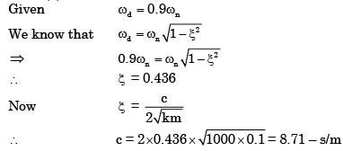
In a spring-mass system, the mass is 0.1 kg and the stiffness of the spring is 1 kN/m. By introducing a damper, the frequency of oscillation is found to be 90% of the original value. What is the damping coefficient of the damper?- a)1.2 N.s/m
- b)3.4 N.s/m
- c)8.7 N.s/m
- d)12.0 N.s/m
Correct answer is option 'C'. Can you explain this answer?
In a spring-mass system, the mass is 0.1 kg and the stiffness of the spring is 1 kN/m. By introducing a damper, the frequency of oscillation is found to be 90% of the original value. What is the damping coefficient of the damper?
a)
1.2 N.s/m
b)
3.4 N.s/m
c)
8.7 N.s/m
d)
12.0 N.s/m
|
|
Sandeep Sengupta answered |
The gears employed for connecting two non-intersecting and non-parallel, i.e., non coplanar shafts are- a)Bevel gears
- b)Spiral gears
- c)Helical gears
- d)Mitre gears
Correct answer is option 'B'. Can you explain this answer?
The gears employed for connecting two non-intersecting and non-parallel, i.e., non coplanar shafts are
a)
Bevel gears
b)
Spiral gears
c)
Helical gears
d)
Mitre gears
|
|
Ananya Kumari answered |
The gears employees for connecting two non intersection
and non about here of
spiral ans
and non about here of
spiral ans
The Carioles component of acceleration is present [GATE-2002]- a)4-bar mechanisms with 4 turning pairs
- b)shaper mechanism
- c)slider-crank mechanism
- d)Scotch Yoke mechanism
Correct answer is option 'B'. Can you explain this answer?
The Carioles component of acceleration is present
[GATE-2002]
a)
4-bar mechanisms with 4 turning pairs
b)
shaper mechanism
c)
slider-crank mechanism
d)
Scotch Yoke mechanism
|
|
Anjali Shah answered |
Explanation:
The question is related to the component of acceleration present in different mechanisms. Let's discuss each option and find out the correct answer.
a) 4-bar mechanisms with 4 turning pairs:
A 4-bar mechanism consists of four links connected by four turning pairs. The turning pairs can be revolute or prismatic joints. This mechanism is widely used in various applications such as engines, machines, and robotics. However, the component of acceleration present in this mechanism is not related to the question. Therefore, option A is not correct.
b) Shaper mechanism:
The shaper mechanism is a type of reciprocating machine tool. It is used to produce flat or curved surfaces on a workpiece. This mechanism consists of a ram, a cutting tool, and a worktable. The component of acceleration present in this mechanism is the Carioles component of acceleration. Therefore, option B is correct.
c) Slider-crank mechanism:
The slider-crank mechanism is a type of reciprocating mechanism used in engines, pumps, and compressors. It consists of a piston, a connecting rod, and a crankshaft. The component of acceleration present in this mechanism is the tangential component of acceleration. Therefore, option C is not correct.
d) Scotch Yoke mechanism:
The Scotch Yoke mechanism is a type of reciprocating mechanism used in engines and compressors. It consists of a yoke, a piston, and a crankshaft. The component of acceleration present in this mechanism is the radial component of acceleration. Therefore, option D is not correct.
Conclusion:
From the above explanation, we can conclude that the correct answer is option B, i.e., Shaper mechanism. The Carioles component of acceleration is present in the shaper mechanism.
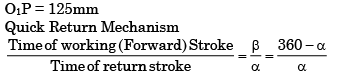
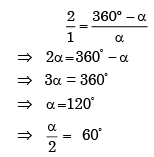
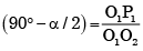
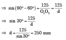
A simple quick return mechanism is shown in the figure. The forward to return ratio of the quick return mechanism is 2: 1. If the radius of the crank O1P is 125 mm, then the distance 'd' (in mm) between the crank centre to lever pivot centre point should be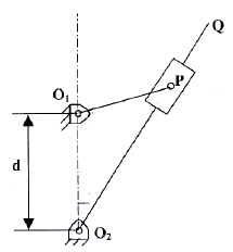
- a)144.3
- b)216.5
- c)240.0
- d)250.0
Correct answer is option 'D'. Can you explain this answer?
A simple quick return mechanism is shown in the figure. The forward to return ratio of the quick return mechanism is 2: 1. If the radius of the crank O1P is 125 mm, then the distance 'd' (in mm) between the crank centre to lever pivot centre point should be
a)
144.3
b)
216.5
c)
240.0
d)
250.0
|
|
Ayush Mukherjee answered |
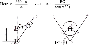
The extreme position of the crank (O1P) are shown in figure.
From right triangle O2O1P1, we find that sin
A single cylinder, four-stroke I.C. engine rotating at 900 rpm has a crank length of 50 mm and a connecting rod length of 200 mm. if the effective reciprocating mass of the engine is 1.2 kg, what is the approximate magnitude of the maximum ‘shaking force’ created by the engine?- a)533 N
- b)666 N
- c)133 N
- d)None of the above
Correct answer is option 'B'. Can you explain this answer?
A single cylinder, four-stroke I.C. engine rotating at 900 rpm has a crank length of 50 mm and a connecting rod length of 200 mm. if the effective reciprocating mass of the engine is 1.2 kg, what is the approximate magnitude of the maximum ‘shaking force’ created by the engine?
a)
533 N
b)
666 N
c)
133 N
d)
None of the above
|
|
Nitin Joshi answered |
Maximum Secondary force Maximum shaking force
= mw2r {cosq + (cos 2q / n)}
[n = (l/r) = (200/50) = 4]
= 1.2 {(2p x 900) / 60}2 x 50 x 10-3 (1+(1/4))
(at q = 0°)
f = 666 N.
= mw2r {cosq + (cos 2q / n)}
[n = (l/r) = (200/50) = 4]
= 1.2 {(2p x 900) / 60}2 x 50 x 10-3 (1+(1/4))
(at q = 0°)
f = 666 N.


Chapter doubts & questions for Theory of Machines (TOM) - GATE Mechanical (ME) Mock Test Series 2026 2025 is part of Mechanical Engineering exam preparation. The chapters have been prepared according to the Mechanical Engineering exam syllabus. The Chapter doubts & questions, notes, tests & MCQs are made for Mechanical Engineering 2025 Exam. Find important definitions, questions, notes, meanings, examples, exercises, MCQs and online tests here.
Chapter doubts & questions of Theory of Machines (TOM) - GATE Mechanical (ME) Mock Test Series 2026 in English & Hindi are available as part of Mechanical Engineering exam.
Download more important topics, notes, lectures and mock test series for Mechanical Engineering Exam by signing up for free.
GATE Mechanical (ME) Mock Test Series 2026
30 docs|220 tests
|
|
© EduRev
|
Education Revolution
|


|


Signup on EduRev and stay on top of your study goals
10M+ students crushing their study goals daily