


All questions of Estimation & Costing for Electrical Engineering (EE) Exam
What is the minimum clearance of HV Lines from ground across streets?- a)3.1 meters
- b)8.1 meters
- c)6.1 meters
- d)5.1 meters
Correct answer is option 'C'. Can you explain this answer?
What is the minimum clearance of HV Lines from ground across streets?
a)
3.1 meters
b)
8.1 meters
c)
6.1 meters
d)
5.1 meters

|
EduRev GATE answered |
According to IE rule 77,
No conductor of an overhead line, including service lines, erected across a street shall at any part thereof be at a height less than -
(a) For low and medium voltage lines - 5.8 metres
(b) For high voltage lines - 6.1 metres

When a high voltage overhead line passes over or adjacent to any building the vertical clearance between the highest part of the building immediately under such liner, recommended in IE rules is of not less than:- a)1.2 m
- b)2.8 m
- c)6 m
- d)3.7 m
Correct answer is option 'D'. Can you explain this answer?
When a high voltage overhead line passes over or adjacent to any building the vertical clearance between the highest part of the building immediately under such liner, recommended in IE rules is of not less than:
a)
1.2 m
b)
2.8 m
c)
6 m
d)
3.7 m

|
Prerna Menon answered |
According to IE rule 80,
Where a high or extra-high voltage over-head line passes above or adjacent to any building or part of a building it shall have on the basis of maximum sag a vertical clearance above the highest part of the building immediately under such line, of not less than
(a) For high voltage lines up to and including 33,000 volts - 3.7 metres
(b) For extra-high voltage lines - 3.7 metres plus 0.3 metre for every additional 33,000 volts or part thereof
The earthing electrodes should be placed within what distance in meters from the building whose installation system is being earthed- a)4
- b)2.5
- c)1.5
- d)0.5
Correct answer is option 'C'. Can you explain this answer?
The earthing electrodes should be placed within what distance in meters from the building whose installation system is being earthed
a)
4
b)
2.5
c)
1.5
d)
0.5
|
|
Jaya Rane answered |
Distance of Earthing Electrodes from Building
The distance of earthing electrodes from the building is an important factor to consider while designing an earthing system for a building. The correct distance ensures safety and effective operation of the electrical installation.
Correct Answer: Option C (1.5 meters)
Explanation:
The earthing electrodes should be placed within 1.5 meters from the building whose installation system is being earthed. This distance is specified in the Indian Electricity Rules (1956).
Reasons for the 1.5-meter distance:
1. Safety: The earthing electrodes provide a low resistance path for the fault current to flow. If the distance between the electrodes and the building is too large, the fault current may find an alternate path through the soil, which may lead to electric shock or fire hazard.
2. Effective Operation: The earthing system is designed to protect the electrical installation from overvoltage and other electrical faults. Placing the earthing electrodes within 1.5 meters ensures that the system operates effectively and provides the required protection.
Conclusion:
In conclusion, the correct distance of earthing electrodes from the building is 1.5 meters. This distance ensures safety and effective operation of the electrical installation. The distance should be adhered to while designing and installing an earthing system for a building.
The type of wiring that is highly suitable for a temporary shed is- a)Cleat wiring
- b)Wooden capping and casing wiring
- c)Lead sheathed wiring
- d)Conduit wiring
Correct answer is option 'A'. Can you explain this answer?
The type of wiring that is highly suitable for a temporary shed is
a)
Cleat wiring
b)
Wooden capping and casing wiring
c)
Lead sheathed wiring
d)
Conduit wiring
|
|
Ajay Mittal answered |
Cleat wiring is most suitable for a temporary shed.
The effect of electric shock on human body depends on:i. Currentii. Voltageiii. Duration of contact- a)Only i
- b)Only ii
- c)Only iii
- d)All i, ii & iii
Correct answer is option 'D'. Can you explain this answer?
The effect of electric shock on human body depends on:
i. Current
ii. Voltage
iii. Duration of contact
a)
Only i
b)
Only ii
c)
Only iii
d)
All i, ii & iii
|
|
Poulomi Ahuja answered |
The effect of electric shock on human body depends on current, voltage and the duration of contact.
What is the maximum load that can be connected in a circuit connecting only lighting points?- a)500 watts
- b)750 watts
- c)800 watts
- d)1000 watts
Correct answer is option 'C'. Can you explain this answer?
What is the maximum load that can be connected in a circuit connecting only lighting points?
a)
500 watts
b)
750 watts
c)
800 watts
d)
1000 watts
|
|
Malavika Nair answered |
In a circuit connecting only lighting points, the maximum load that can be connected is determined by the current rating of the circuit and the wattage of each lighting point.
1. Current rating of the circuit:
The current rating of a circuit is determined by the rating of the protective device, such as a fuse or a circuit breaker. This rating is usually specified in amperes (A). To calculate the maximum load that can be connected, we need to know the current rating of the circuit.
2. Wattage of each lighting point:
The wattage of each lighting point refers to the power consumption of the light bulbs or fixtures that are connected to the circuit. This wattage is usually specified in watts (W). To calculate the maximum load that can be connected, we need to know the wattage of each lighting point.
3. Calculation:
To determine the maximum load that can be connected in the circuit, we can use the formula:
Maximum Load (in watts) = Current Rating (in amperes) x Voltage (in volts)
Since the voltage is not given in the question, we can assume a standard voltage of 120 volts for residential lighting circuits.
Let's consider the options given in the question:
a) 500 watts: This option does not provide any information about the current rating of the circuit, so we cannot determine if it is the correct answer.
b) 750 watts: This option does not provide any information about the current rating of the circuit, so we cannot determine if it is the correct answer.
c) 800 watts: This option does not provide any information about the current rating of the circuit, so we cannot determine if it is the correct answer.
d) 1000 watts: This option does not provide any information about the current rating of the circuit, so we cannot determine if it is the correct answer.
Since none of the options provide the necessary information to calculate the maximum load, we cannot determine the correct answer based on the given options.
Normally the human body resistance in totally wet and dry condition is ________ respectively.- a)1 k Ω and 1 MΩ
- b)0.1 Ω and 10 kΩ
- c)100 Ω and 1 kΩ
- d)100 Ω and 10 kΩ
Correct answer is option 'A'. Can you explain this answer?
Normally the human body resistance in totally wet and dry condition is ________ respectively.
a)
1 k Ω and 1 MΩ
b)
0.1 Ω and 10 kΩ
c)
100 Ω and 1 kΩ
d)
100 Ω and 10 kΩ
|
|
Samridhi Bose answered |
Under dry conditions, the resistance offered by the human body may be as high as one mega ohms. Wet or broken skin may drop the body's resistance to 1000 ohms. Adding that, high-voltage electrical energy quickly breaks down human skin, reducing the human body's resistance to 500 ohms.
What is the factor of safety used for current ratings in a power installation?- a)1
- b)1.5
- c)1.75
- d)2
Correct answer is option 'D'. Can you explain this answer?
What is the factor of safety used for current ratings in a power installation?
a)
1
b)
1.5
c)
1.75
d)
2
|
|
Ankita Das answered |
Factor of safety describes the load carrying capacity of a system beyond the expected or actual loads. The factor of safety used for current ratings in a power installation is 2
For reducing tower footing resistance, it is better to use- a)Chemical and ground rod only
- b)Chemical and counterpoise only
- c)Ground rod and counterpoise only
- d)None of these
Correct answer is option 'C'. Can you explain this answer?
For reducing tower footing resistance, it is better to use
a)
Chemical and ground rod only
b)
Chemical and counterpoise only
c)
Ground rod and counterpoise only
d)
None of these
|
|
Madhurima Das answered |
Tower footing resistance is the resistance offered by the tower footing to the dissipation of ground. The effective ground wire depends to a large extend on the tower footing resistance. The tower top potential depends on this resistance.
Low value of tower footing resistance results in less voltage stresses across line insulation. A tower footing resistance of 20 ohm for EHV lines and 10 ohm for HV lines provides sufficient lightning protection.
Tower footing resistance depends on
1) Type of electrode configuration employed
2) Soil resistivity
3) Electrode shapes (Hemisphere, vertical driven rod, and Buried horizontal wires)
Methods for tower grounding are:
Buried Conductor: One or more conductors are connected to tower legs and buried in back filled of tower foundation. It is used when soil resistivity is low
Counterpoise Wire: A wire/ Strip of length of 50 m is buried horizontally at depth of 0.5 m below ground. This wire is connected to tower legs. It is used when earth resistance is very high and soil conductivity is mostly confined to upper layer
Ground rod: Pipe/Rod of 3 to 4 m is driven into ground near the tower and top of rod is connected to tower by suitable wire/strip. It is used where ground conductivity increase with depth
Treated Earth Pits: Pipe/Rod of 3 to 4 m are buried in treated earth pits and top of rod is connected to tower by suitable wire/strip. It is used in very high resistivity near tower
For reducing tower footing resistance, it is better to use ground rod and counterpoise only.
Earth resistance comprises ofA. Resistance of soil away from electrodeB. Contact resistance between electrode and soilC. Resistance of metal electrode- a)A only
- b)A and B only
- c)A and C only
- d)A, B and C together
Correct answer is option 'D'. Can you explain this answer?
Earth resistance comprises of
A. Resistance of soil away from electrode
B. Contact resistance between electrode and soil
C. Resistance of metal electrode
a)
A only
b)
A and B only
c)
A and C only
d)
A, B and C together
|
|
Rajveer Saha answered |
The resistance offered by the earth electrode to the flow of current into the ground is known as the earth resistance or resistance to earth. It comprises of
1) Resistance of soil away from electrode
2) Contact resistance between electrode and soil
3) Resistance of metal electrode
Which material is used for wiring continuous bus bar?i. Aluminumii. Copper- a)Only i
- b)Only ii
- c)Both I and ii
- d)None of these
Correct answer is option 'A'. Can you explain this answer?
Which material is used for wiring continuous bus bar?
i. Aluminum
ii. Copper
a)
Only i
b)
Only ii
c)
Both I and ii
d)
None of these
|
|
Tanishq Majumdar answered |
Aluminum is used for wiring continuous bus bar because its cost is lesser than the copper.
As per IE rules the maximum allowable variation between declared and actual voltage at consumer’s premises should be- a)± 4 %
- b)± 4.5 %
- c)± 3 %
- d)± 3.5 %
Correct answer is option 'C'. Can you explain this answer?
As per IE rules the maximum allowable variation between declared and actual voltage at consumer’s premises should be
a)
± 4 %
b)
± 4.5 %
c)
± 3 %
d)
± 3.5 %
|
|
Mansi Choudhury answered |
As per IE rules the maximum allowable variation between declared and actual voltage at consumer’s premises should be ± 3%
In which type of wiring vulcanized Indian rubber (VIR) and polyvinyl chloride (PVC) insulated wires are used as conductors- a)CTS wiring
- b)Cleat wiring
- c)Lead sheathed wiring
- d)Conduit wiring
Correct answer is option 'B'. Can you explain this answer?
In which type of wiring vulcanized Indian rubber (VIR) and polyvinyl chloride (PVC) insulated wires are used as conductors
a)
CTS wiring
b)
Cleat wiring
c)
Lead sheathed wiring
d)
Conduit wiring
|
|
Samridhi Bose answered |
Vulcanized Indian Rubber: These consists of a copper conductor covered with an insulation layer of VIR. A cotton tape covering is provided over this insulation layer to protect the wire from moisture and to provide mechanical strength to the wire. These type of wires are used in 250 V CTS wiring, casing or capping or cleat wiring.
Polyvinyl Chloride: These wires consists of a conductor over which an insulation layer made up of Polyvinyl Chloride is provided. These wires cannot resist much heat and they have relatively low melting points, so they aren’t used in hot places and also these wires are not used with heating appliances. These wires are applied in casing wiring and also used along with cleat wiring
Mixture preferred for filling around the earth electrode for effective earthing is:- a)Pepper-salt mixture
- b)Saw dust mixture
- c)Coal-salt mixture
- d)Lime-sand mixture
Correct answer is option 'C'. Can you explain this answer?
Mixture preferred for filling around the earth electrode for effective earthing is:
a)
Pepper-salt mixture
b)
Saw dust mixture
c)
Coal-salt mixture
d)
Lime-sand mixture
|
|
Arindam Sengupta answered |
The correct answer is option 'C' - Lime-sand mixture.
Explanation:
Effective earthing is crucial for the safety and proper functioning of electrical systems. It helps to dissipate fault currents, prevent electric shocks, and protect equipment from damage. The choice of mixture for filling around the earth electrode is important as it affects the conductivity and stability of the earthing system.
Here are the reasons why lime-sand mixture is preferred for filling around the earth electrode:
1. Conductivity: Lime-sand mixture has good electrical conductivity, which is essential for effective earthing. It allows the fault currents to flow efficiently through the earth electrode and dissipate into the ground.
2. Moisture retention: Lime-sand mixture has the ability to retain moisture, which helps in maintaining a low resistance path for current flow. Moisture is important for reducing the resistance between the earth electrode and the surrounding soil, ensuring effective earthing.
3. Chemical resistance: Lime has high chemical resistance, making it suitable for use in various types of soil conditions. It does not easily degrade or react with different soil compositions, ensuring long-term stability of the earthing system.
4. Mechanical stability: Lime-sand mixture provides good mechanical stability to the earthing system. It prevents the earth electrode from shifting or moving due to external factors such as wind, vibration, or soil settlement. This stability is important to maintain the integrity of the earthing system over time.
5. Cost-effectiveness: Lime-sand mixture is relatively inexpensive compared to other mixtures such as coal-salt or pepper-salt. It provides a cost-effective solution for filling around the earth electrode without compromising on the performance of the earthing system.
In conclusion, lime-sand mixture is preferred for filling around the earth electrode for effective earthing due to its good electrical conductivity, moisture retention capability, chemical resistance, mechanical stability, and cost-effectiveness. It ensures a low-resistance path for fault currents, maintains the stability of the earth electrode, and provides long-term performance of the earthing system.
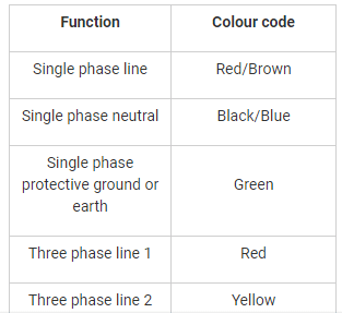
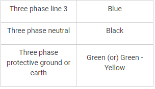
In house wiring, black & green wires indicate- a)Earth & Neutral respectively
- b)Phase & Neutral respectively
- c)Phase & Earth respectively
- d)Neutral & Earth respectively
Correct answer is option 'D'. Can you explain this answer?
In house wiring, black & green wires indicate
a)
Earth & Neutral respectively
b)
Phase & Neutral respectively
c)
Phase & Earth respectively
d)
Neutral & Earth respectively
|
|
Raj Singh answered |
Understanding House Wiring Colors
In house wiring, color codes are essential for safety and functionality. Different colors designate specific roles in electrical systems.
Wire Color Codes
- Black Wire: Typically represents the Phase (or live) wire. It carries current to the load.
- Green Wire: This is generally used for Earth (or ground) connections. It provides a safe path for stray electricity, protecting users from electric shock.
Correct Answer Explanation
The correct answer is option 'D' (Neutral & Earth respectively). However, it’s important to clarify that:
- Neutral Wire is usually characterized by a blue color in many standards, while green or green/yellow is reserved for earth connections.
- In some wiring systems, black can also be utilized for neutral, but in standard practices, it is primarily for phase connections.
Importance of Color Codes
- Safety: Following standardized color codes prevents accidental connections that could lead to short circuits or electrocution.
- Identification: Using correct colors helps electricians quickly identify the function of each wire during installations and repairs.
Conclusion
In summary, the black wire is associated with the phase, while the green wire indicates earth connections in electrical systems. For clarity, ensure that you refer to local electrical code standards as they may vary by region. Always prioritize safety by adhering to these color conventions when working with electrical wiring.
As per IE rules the permissible variation of voltage at the consumer end is:- a)±6%
- b)±10%
- c)±12%
- d)±2%
Correct answer is option 'A'. Can you explain this answer?
As per IE rules the permissible variation of voltage at the consumer end is:
a)
±6%
b)
±10%
c)
±12%
d)
±2%
|
|
Saranya Mishra answered |
As per IE rules the permissible variation of voltage at the consumer end is ±6%.
In the case of low or medium voltage, it is more than 6 percent.
In the case of high voltage, it is more than 6 per cent on the higher side or by more than 9 per cent on the lower side.
The earth’s potential is taken is –- a)Infinite
- b)Supply voltage
- c)1 volt
- d)Zero
Correct answer is option 'D'. Can you explain this answer?
The earth’s potential is taken is –
a)
Infinite
b)
Supply voltage
c)
1 volt
d)
Zero
|
|
Samridhi Bose answered |
Earth is chosen as a place of zero electric potential because it has almost constant potential.
For the measurement of the earth resistance of a given earth electrode:- a)Collecting electrode should be very near to the electrode under test
- b)Collecting electrode should touch the electrode under test
- c)Collecting electrode should be far way the electrode under test
- d)None of these
Correct answer is option 'C'. Can you explain this answer?
For the measurement of the earth resistance of a given earth electrode:
a)
Collecting electrode should be very near to the electrode under test
b)
Collecting electrode should touch the electrode under test
c)
Collecting electrode should be far way the electrode under test
d)
None of these
|
|
Sneha Bose answered |
Measurement of Earth Resistance:
Collecting electrode distance:
The correct answer is option 'C', which states that the collecting electrode should be far away from the electrode under test for the measurement of earth resistance. This is because if the collecting electrode is too close to the electrode under test, it may affect the measurement due to the influence of the test current on the electrode. Therefore, proper distance between the electrodes is crucial for accurate measurement.
Factors affecting distance:
There are several factors that can affect the distance between the electrodes, including the size and shape of the electrodes, the depth of the test, and the soil resistance. In general, a distance of at least 20 times the depth of the electrode is recommended for accurate measurement.
Procedure:
The procedure for measuring earth resistance involves connecting the test electrode to the earth and injecting a test current into the earth. The voltage drop between the test electrode and the collecting electrode is then measured, and the earth resistance is calculated using Ohm's law.
Conclusion:
In conclusion, the correct distance between the electrodes is essential for accurate measurement of earth resistance. The collecting electrode should be far away from the electrode under test, and a distance of at least 20 times the depth of the electrode is recommended for accurate measurement. The procedure involves injecting a test current and measuring the voltage drop, and the earth resistance is calculated using Ohm's law.
Overhead lines for power supply to tram cars are at a minimum height of- a)3 m
- b)6 m
- c)10 m
- d)20 m
Correct answer is option 'C'. Can you explain this answer?
Overhead lines for power supply to tram cars are at a minimum height of
a)
3 m
b)
6 m
c)
10 m
d)
20 m
|
|
Athira Pillai answered |
According to IE rules, Overhead lines for power supply to tram cars are should be at a minimum height of 10 m
What is the minimum permissible size of the earth continuity conductor?- a)6 sq. mm
- b)9 sq. mm
- c)11 sq. mm
- d)13 sq. mm
Correct answer is option 'A'. Can you explain this answer?
What is the minimum permissible size of the earth continuity conductor?
a)
6 sq. mm
b)
9 sq. mm
c)
11 sq. mm
d)
13 sq. mm
|
|
Hiral Kulkarni answered |
The minimum permissible size of the earth continuity conductor is 6 sq. mm.
Which type of neutral grounding method has high transient voltages appear under fault conditions?- a)Solid grounding
- b)Resistance grounding
- c)Reactance grounding
- d)Plate grounding
Correct answer is option 'C'. Can you explain this answer?
Which type of neutral grounding method has high transient voltages appear under fault conditions?
a)
Solid grounding
b)
Resistance grounding
c)
Reactance grounding
d)
Plate grounding
|
|
Sanchita Choudhary answered |
Solid grounding: In this type of neutral grounding, the neutral of the system is directly connected to the ground through a conductor of negligible resistance and reactance.
Resistance grounding: In this type of neutral grounding, the neutral of the system is connected to ground through one or more resistance. Resistance grounding limits the fault currents. It protects the system from transient over voltages
Reactance grounding: In this method, a reactance is inserted between the neutral and ground to limit the fault current. This method has high transient voltages appear under fault conditions
In practice, Earth is chosen as a place of zero electric potential because it:- a)Is non-conducting
- b)Is easily available reference
- c)Keeps losing and gaining electric charge every day
- d)Has almost constant potential
Correct answer is option 'D'. Can you explain this answer?
In practice, Earth is chosen as a place of zero electric potential because it:
a)
Is non-conducting
b)
Is easily available reference
c)
Keeps losing and gaining electric charge every day
d)
Has almost constant potential
|
|
Srestha Kumar answered |
Zero Electric Potential
Zero electric potential is a reference point used in electrical engineering and physics to measure the electric potential at other points in a system. In practice, Earth is often chosen as the place of zero electric potential. This choice is based on several factors, including its almost constant potential.
Constant Potential of Earth
The Earth's electric potential remains relatively constant due to the presence of a large conductive surface, such as the Earth's surface itself, which acts as a "ground". This means that the potential difference between any point on the Earth's surface and another point on the Earth's surface is essentially zero. By convention, this is chosen as the reference point for measuring electric potential.
Non-Conducting Earth
It is important to note that the choice of Earth as the reference point for zero electric potential does not depend on whether the Earth is conducting or non-conducting. In fact, the Earth's surface is a good conductor of electricity, as it is made up of materials such as soil and water that contain free charges. However, the choice of Earth as the reference point is not based on the conductivity of the Earth.
Easily Available Reference
Another reason why Earth is chosen as the reference point for zero electric potential is its easy availability. Earth is present everywhere, and it is easily accessible for measurements. This makes it convenient to use Earth as the reference point in electrical engineering and physics experiments.
Loss and Gain of Electric Charge
The fact that Earth keeps losing and gaining electric charge every day does not directly influence the choice of Earth as the reference point for zero electric potential. The loss and gain of electric charge by Earth are natural processes that occur due to various factors such as lightning, atmospheric conditions, and the interaction of Earth with other charged objects. These processes do not affect the overall constant potential of Earth, which is the primary reason for choosing it as the reference point.
In conclusion, Earth is chosen as the place of zero electric potential because it has an almost constant potential, it is easily available as a reference, and its conductivity does not play a significant role in this choice.
The addition of ground rods in the earthing grid:- a)Decrease the earth resistance
- b)Has no effect on earth resistance
- c)Slightly decrease the earth resistance
- d)Slightly increase the earth resistance
Correct answer is option 'C'. Can you explain this answer?
The addition of ground rods in the earthing grid:
a)
Decrease the earth resistance
b)
Has no effect on earth resistance
c)
Slightly decrease the earth resistance
d)
Slightly increase the earth resistance
|
|
Puja Shah answered |
Since the resistance of the earth near each ground rod will be very high, adding a second ground rod we can slightly reduce the overall grounding resistance. Ground rods would need to be spaced 7.6 m apart to achieve the best grounding effect.
In earthed neutral system, the magnitude of transient voltage is:- a)Zero
- b)Vary small
- c)Medium
- d)Very high
Correct answer is option 'B'. Can you explain this answer?
In earthed neutral system, the magnitude of transient voltage is:
a)
Zero
b)
Vary small
c)
Medium
d)
Very high
|
|
Sanskriti Desai answered |
In earthed neutral system, the neutral is earthed either directly or through resistance or reactance depends on the requirement.
The advantages of neutral earthing are,
1. The arcing grounds are prevented from occurring by employing suitable switchgears
2. As the neutral point is not shifted in this system, thus the voltages of healthy phase’s remains nearly constant
3. The faulty part of the system can be isolated from the remaining system with the help of earth fault relays
4. The magnitude of transient voltage is very small
5. This is system is more reliable, provides safety to personnel and equipment with reduced operational and maintenance cost than ungrounded system
For proper earthing, what should be the maximum value of earth resistance while carrying out the testing of earth continuity path?- a)1 Ω
- b)2 Ω
- c)5 Ω
- d)10 Ω
Correct answer is option 'A'. Can you explain this answer?
For proper earthing, what should be the maximum value of earth resistance while carrying out the testing of earth continuity path?
a)
1 Ω
b)
2 Ω
c)
5 Ω
d)
10 Ω
|
|
Bijoy Nair answered |
Maximum Value of Earth Resistance for Proper Earthing
Earth resistance is a crucial factor in ensuring proper earthing for electrical systems. The maximum value of earth resistance plays a significant role in determining the effectiveness of the earth continuity path.
1 Ω - The Correct Maximum Value
- The correct maximum value of earth resistance while carrying out testing of the earth continuity path is 1 Ω.
- This value ensures that the path for electrical current to flow to the ground is low enough to prevent any potential safety hazards.
- Keeping the earth resistance below 1 Ω helps in maintaining a low impedance path for fault currents to be safely dissipated into the ground.
- It also ensures that the electrical system remains properly grounded, reducing the risk of electric shocks and equipment damage.
Importance of Low Earth Resistance
- Low earth resistance is essential for providing effective protection against electrical faults and overcurrent situations.
- It helps in maintaining the integrity of the grounding system, ensuring proper functioning of protective devices like circuit breakers and fuses.
- By keeping the earth resistance below 1 Ω, the risk of voltage gradients and potential differences is minimized, enhancing the safety of the electrical installation.
In conclusion, maintaining the earth resistance below 1 Ω is crucial for proper earthing and ensuring the safety and reliability of electrical systems. It is important to conduct regular testing of the earth continuity path to verify that the resistance value is within the acceptable range.
Which statement is true, with respect to the motor installation?- a)Wood work is used for mounting switchgears
- b)All equipment used in power wiring shall be of iron clad
- c)Looping of conductors is usually made
- d)The length of flexible conduit is more than 3 m
Correct answer is option 'B'. Can you explain this answer?
Which statement is true, with respect to the motor installation?
a)
Wood work is used for mounting switchgears
b)
All equipment used in power wiring shall be of iron clad
c)
Looping of conductors is usually made
d)
The length of flexible conduit is more than 3 m
|
|
Mihir Chawla answered |
1. Wood is not used for mounting switchgears
2. All equipment used in power wiring shall be of iron clad
3. Electrical looping is loop/loops created between two light with 1 single wire connected to multiple fittings. Usually looping is done for neutral wire. Neutral wire is a return wire for the current in an electrical circuit, i.e. it carries electricity from the output device back to the service panel/board
4. The length of flexible conduit is less than 1.8 m
While using wooden poles in a services line, the span should not exceed- a)100 to 300 m
- b)60 to 100 m
- c)50 to 80 m
- d)40 to 50 m
Correct answer is option 'D'. Can you explain this answer?
While using wooden poles in a services line, the span should not exceed
a)
100 to 300 m
b)
60 to 100 m
c)
50 to 80 m
d)
40 to 50 m
|
|
Jyoti Basak answered |
Wooden Poles in a Services Line
Wooden poles are commonly used in electrical services lines for distributing electricity from the main power source to residential and commercial buildings. However, there are certain limitations and guidelines that need to be followed to ensure the safety and reliability of the electrical distribution system. One such limitation is the maximum span length between wooden poles.
The span length refers to the distance between two consecutive wooden poles in a services line. It is crucial to determine the appropriate span length to maintain the structural integrity of the poles and prevent sagging of the overhead conductors. Sagging can lead to a variety of issues, including electrical short circuits, increased line losses, and potential hazards for both the electrical system and surrounding environment.
According to the given options, the correct answer is option 'D' - 40 to 50 meters. Ideally, the span length for wooden poles in a services line should not exceed this range. Let's understand why this recommendation is made.
Several factors influence the recommended span length for wooden poles in a services line. These factors include:
1. Pole Strength: Wooden poles have inherent strength limitations. They may not be able to withstand excessive load or stress over long distances, leading to structural failures.
2. Weight of Conductors: The weight of the overhead conductors supported by the poles is an important consideration. Heavier conductors exert more downward force, causing greater sagging and potential pole deflection.
3. Wind Load: Wind can exert significant lateral forces on the overhead conductors, increasing the overall stress on the poles. Longer spans are more susceptible to wind-induced vibrations and may compromise the stability of the entire line.
4. Safety and Accessibility: Shorter span lengths allow for easier maintenance and inspection of the electrical system. It is important to ensure that workers can safely access the poles and conduct routine checks without any difficulties.
Among the given options, option 'D' (40 to 50 meters) is the most appropriate span length for wooden poles in a services line. This range strikes a balance between structural integrity, conductor sagging, wind load considerations, and maintenance accessibility. Span lengths within this range offer sufficient support to the conductors, minimize sagging, and reduce the risk of pole failure.
In conclusion, the span length for wooden poles in a services line should not exceed 40 to 50 meters to ensure the safety, reliability, and longevity of the electrical distribution system. Adhering to this recommended range helps in preventing sagging of conductors, reducing line losses, and facilitating routine maintenance activities.
Introduction
Wooden poles are commonly used in electrical services lines for distributing electricity from the main power source to residential and commercial buildings. However, there are certain limitations and guidelines that need to be followed to ensure the safety and reliability of the electrical distribution system. One such limitation is the maximum span length between wooden poles.
Importance of Span Length
The span length refers to the distance between two consecutive wooden poles in a services line. It is crucial to determine the appropriate span length to maintain the structural integrity of the poles and prevent sagging of the overhead conductors. Sagging can lead to a variety of issues, including electrical short circuits, increased line losses, and potential hazards for both the electrical system and surrounding environment.
Recommended Span Length
According to the given options, the correct answer is option 'D' - 40 to 50 meters. Ideally, the span length for wooden poles in a services line should not exceed this range. Let's understand why this recommendation is made.
Factors Influencing Span Length
Several factors influence the recommended span length for wooden poles in a services line. These factors include:
1. Pole Strength: Wooden poles have inherent strength limitations. They may not be able to withstand excessive load or stress over long distances, leading to structural failures.
2. Weight of Conductors: The weight of the overhead conductors supported by the poles is an important consideration. Heavier conductors exert more downward force, causing greater sagging and potential pole deflection.
3. Wind Load: Wind can exert significant lateral forces on the overhead conductors, increasing the overall stress on the poles. Longer spans are more susceptible to wind-induced vibrations and may compromise the stability of the entire line.
4. Safety and Accessibility: Shorter span lengths allow for easier maintenance and inspection of the electrical system. It is important to ensure that workers can safely access the poles and conduct routine checks without any difficulties.
Reason for Option 'D' as the Correct Answer
Among the given options, option 'D' (40 to 50 meters) is the most appropriate span length for wooden poles in a services line. This range strikes a balance between structural integrity, conductor sagging, wind load considerations, and maintenance accessibility. Span lengths within this range offer sufficient support to the conductors, minimize sagging, and reduce the risk of pole failure.
Conclusion
In conclusion, the span length for wooden poles in a services line should not exceed 40 to 50 meters to ensure the safety, reliability, and longevity of the electrical distribution system. Adhering to this recommended range helps in preventing sagging of conductors, reducing line losses, and facilitating routine maintenance activities.
Minimum distance of underground cable from the foundation of building should be- a)100 cm
- b)50 cm
- c)10 cm
- d)5 cm
Correct answer is option 'C'. Can you explain this answer?
Minimum distance of underground cable from the foundation of building should be
a)
100 cm
b)
50 cm
c)
10 cm
d)
5 cm
|
|
Bibek Saha answered |
As per IE rules Minimum distance of underground cable from the foundation of building should be 10 cm.
What is meant by contingencies?i. The list of required components are included in this categoryii. The list of vague and unforeseen items is included in this categoryiii. The list of components along with their discounted prices is included in this category- a)Only i
- b)Only ii
- c)Only iii
- d)Both ii and iii
Correct answer is option 'B'. Can you explain this answer?
What is meant by contingencies?
i. The list of required components are included in this category
ii. The list of vague and unforeseen items is included in this category
iii. The list of components along with their discounted prices is included in this category
a)
Only i
b)
Only ii
c)
Only iii
d)
Both ii and iii
|
|
Palak Verma answered |
Contingencies in Electrical Engineering
Contingencies in electrical engineering refer to unexpected or unforeseen events, situations, or conditions that may arise during the design, construction, or operation of electrical systems. These contingencies are typically accounted for in planning and budgeting processes to ensure that projects are completed successfully and within the allocated resources.
Explanation of the Options
i. The list of required components are included in this category: This option is incorrect. The list of required components is not considered a contingency. Required components are typically identified and included in the project plan and budget.
ii. The list of vague and unforeseen items is included in this category: This option is correct. Contingencies often include a list of vague and unforeseen items that may arise during a project. These items may include unexpected equipment failures, changes in scope, delays, or unforeseen technical challenges.
iii. The list of components along with their discounted prices is included in this category: This option is incorrect. The list of components along with their discounted prices is not related to contingencies. Discounted prices are typically negotiated and finalized during the procurement process, and they are not considered contingencies.
Significance of Contingencies
Contingencies are an essential aspect of project management in electrical engineering. They provide a buffer for unexpected events and ensure that projects can adapt and respond to unforeseen circumstances without compromising their success. Some key reasons why contingencies are necessary include:
1. Risk Mitigation: Contingencies help to mitigate risks associated with uncertainties in project execution. By allocating resources for contingencies, project managers can address unforeseen challenges and minimize the impact on project timelines and budgets.
2. Flexibility: Contingencies allow for flexibility in project planning and implementation. They provide the necessary cushion to accommodate changes in project scope, unexpected delays, or technical issues that may arise during the project lifecycle.
3. Cost Control: By including contingencies in project budgets, project managers can effectively control project costs. Contingencies help to cover unexpected expenses, preventing cost overruns and ensuring that projects remain within the allocated budget.
4. Stakeholder Satisfaction: Contingencies contribute to stakeholder satisfaction by minimizing disruptions to project timelines and ensuring that project goals are achieved. When unforeseen events occur, having contingencies in place allows project managers to respond promptly and effectively, maintaining stakeholder confidence.
Conclusion
In summary, contingencies in electrical engineering refer to unforeseen events or circumstances that may occur during the design, construction, or operation of electrical systems. They are essential for risk mitigation, flexibility, cost control, and stakeholder satisfaction. The correct option in terms of contingencies is option ii, which includes a list of vague and unforeseen items that may arise during a project.
What is the maximum length of the flexible conduit in motor installation?- a)Less than 1.25 m
- b)Less than 2.25 m
- c)Less than 3.5 m
- d)Can exceed not more than 5 m
Correct answer is option 'A'. Can you explain this answer?
What is the maximum length of the flexible conduit in motor installation?
a)
Less than 1.25 m
b)
Less than 2.25 m
c)
Less than 3.5 m
d)
Can exceed not more than 5 m
|
|
Mayank Sengupta answered |
According to Indian Electricity rules, the maximum length of the flexible conduit in motor installation is should be less than 1.25 m
For what voltage levels are the screwed conduit circuits used?- a)Less than 250 V
- b)Between 250 V - 600 V
- c)Above 600 V
- d)None of these
Correct answer is option 'B'. Can you explain this answer?
For what voltage levels are the screwed conduit circuits used?
a)
Less than 250 V
b)
Between 250 V - 600 V
c)
Above 600 V
d)
None of these
|
|
Anshika Khanna answered |
The screwed conduit circuits are used to protect the electrical wiring. It is used for the voltage levels in between 250 V to 600 V.
What is the dimensions of the copper strips used for the strip earthing?- a)25 mm × 4 mm
- b)25 mm × 3 mm
- c)30 mm × 4 mm
- d)30 mm × 3 mm
Correct answer is option 'A'. Can you explain this answer?
What is the dimensions of the copper strips used for the strip earthing?
a)
25 mm × 4 mm
b)
25 mm × 3 mm
c)
30 mm × 4 mm
d)
30 mm × 3 mm
|
|
Sushant Mehta answered |
In the method of strip earthing, strip electrodes of cross-section not less than 25mm x 1.6mm (1in x 0.06in) is buried in a horizontal trenches of a minimum depth of 0.5m. If copper is used then the dimension will be cross-section of 25mm x 4mm (1in x 0.15in) and if galvanized iron or steel is used then dimension of 3.0 mm2 is used.
In case of electric fire, use:- a)CO2
- b)N2S
- c)SO2
- d)Cl2
Correct answer is option 'A'. Can you explain this answer?
In case of electric fire, use:
a)
CO2
b)
N2S
c)
SO2
d)
Cl2
|
|
Rahul Banerjee answered |
Class C type fire extinguishers can be used for electrical fires. While the extinguishment of electrical fire,
1. If possible, remove the source of energy by unplugging or disconnecting the electrical equipment
2. Use carbon dioxide, ordinary (BC rated) dry chemical, multi-purpose dry chemical and halon fire extinguishers
3. Do not use water on any energized electrical equipment
What is an electrical schedule?i. A list or a plan of a building providing information of number of points in each roomii. The list of all the electrical components required for a particular roomiii. The list all the electrical components along with their prices- a)Only i
- b)Only ii
- c)Both ii and iii
- d)None of these
Correct answer is option 'A'. Can you explain this answer?
What is an electrical schedule?
i. A list or a plan of a building providing information of number of points in each room
ii. The list of all the electrical components required for a particular room
iii. The list all the electrical components along with their prices
a)
Only i
b)
Only ii
c)
Both ii and iii
d)
None of these
|
|
Bijoy Mehta answered |
Electrical schedule is a list or a plan of a building providing information of number of points in each room
One among the following is the top most conductors in high voltage transmission lines, identify it.- a)R- phase conductor
- b)Y- phase conductor
- c)B- phase conductor
- d)Earth conductor
Correct answer is option 'D'. Can you explain this answer?
One among the following is the top most conductors in high voltage transmission lines, identify it.
a)
R- phase conductor
b)
Y- phase conductor
c)
B- phase conductor
d)
Earth conductor
|
|
Muskaan Nair answered |
A guard wire or earth wire is the top most conductors in high voltage transmission lines. It is used mainly to protect lines from lightning. If in case lightning struck then it carries the excessive current inrush to ground.
Its radius is much smaller than the actual transmission wire because as the resistance is inversely proportional to area of cross section and as the cross section decreases, the resistance increases. The increased resistance of earth wire is able to withstand high inrush of current caused due to lightning and it will safely guide this inrush into ground.
Setting depth of poles is- a)1/4 part of the length of pole
- b)1/5 part of the length of pole
- c)1/8 part of the length of pole
- d)1/2 part of the length of pole
Correct answer is option 'B'. Can you explain this answer?
Setting depth of poles is
a)
1/4 part of the length of pole
b)
1/5 part of the length of pole
c)
1/8 part of the length of pole
d)
1/2 part of the length of pole
|
|
Aman Datta answered |
Setting depth of poles is 1/5 part of the length of pole. The depth for most heavy poles should be at least two feet. Another rule of thumb is that the hole’s depth should be 1/5 of the length of the poles and below the frost line.
The aluminium conductor of size ______ is used for sub circuit in domestic wiring- a)

- b)

- c)

- d)

Correct answer is option 'C'. Can you explain this answer?
The aluminium conductor of size ______ is used for sub circuit in domestic wiring
a)
b)
c)
d)

|
Prashanth Mehra answered |
The size of aluminium conductor used for sub circuit in domestic wiring should be
The purpose of earthing electric appliances is:- a)To provide safety against shock
- b)To ensure that the appliances work properly
- c)To ensure that the appliances get full voltage
- d)None of the above
Correct answer is option 'A'. Can you explain this answer?
The purpose of earthing electric appliances is:
a)
To provide safety against shock
b)
To ensure that the appliances work properly
c)
To ensure that the appliances get full voltage
d)
None of the above
|
|
Swati Tiwari answered |
The earthing is essential because,
1. The earthing protects the personnel from the short circuit current hence it provides safety against shock
2. The earthing provides the easiest path to the flow of short circuit current even after the failure of the insulation
3. The earthing protects the apparatus and personnel from the high voltage surges and lightning discharge
Chapter doubts & questions for Estimation & Costing - Mock Test Series for SSC JE Electrical Engineering 2026 2025 is part of Electrical Engineering (EE) exam preparation. The chapters have been prepared according to the Electrical Engineering (EE) exam syllabus. The Chapter doubts & questions, notes, tests & MCQs are made for Electrical Engineering (EE) 2025 Exam. Find important definitions, questions, notes, meanings, examples, exercises, MCQs and online tests here.
Chapter doubts & questions of Estimation & Costing - Mock Test Series for SSC JE Electrical Engineering 2026 in English & Hindi are available as part of Electrical Engineering (EE) exam.
Download more important topics, notes, lectures and mock test series for Electrical Engineering (EE) Exam by signing up for free.
Mock Test Series for SSC JE Electrical Engineering 2026
2 videos|1 docs|55 tests
|
|
© EduRev
|
Education Revolution
|


|


Signup to see your scores
go up within 7 days!
Access 1000+ FREE Docs, Videos and Tests
Takes less than 10 seconds to signup