


All Exams >
Civil Engineering (CE) >
Design of Steel Structures >
All Questions
All questions of Tension Members for Civil Engineering (CE) Exam
A steel plate is 300 mm wide and 10 mm thick. A rivet of nominal diameter 18 mm is driven. The net sectional area of the plate is- a)1800 mm2
- b)2805 mm2
- c)2820 mm2
- d)3242 mm2
Correct answer is option 'B'. Can you explain this answer?
A steel plate is 300 mm wide and 10 mm thick. A rivet of nominal diameter 18 mm is driven. The net sectional area of the plate is
a)
1800 mm2
b)
2805 mm2
c)
2820 mm2
d)
3242 mm2

|
Sankar Rane answered |
Net sectional area of the plate is given by,
Anet = (B - nd) x t
= [300-1 x (18 + 1.5)] x 10
= 2805 mm2
Anet = (B - nd) x t
= [300-1 x (18 + 1.5)] x 10
= 2805 mm2

A tension member, if subjected to possible reversal of stress due to wind or earthquake the slenderness ratio of the member should not exceed- a)180
- b)300
- c)250
- d)350
Correct answer is option 'D'. Can you explain this answer?
A tension member, if subjected to possible reversal of stress due to wind or earthquake the slenderness ratio of the member should not exceed
a)
180
b)
300
c)
250
d)
350

|
Sandeep Sen answered |
Slenderness Ratio for Tension Members
A tension member in a structure is a component that is designed to resist axial tensile forces. Examples of tension members include cables, rods, and tie-rods. When designing a tension member, one of the important considerations is its slenderness ratio.
Definition of Slenderness Ratio
Slenderness ratio is defined as the ratio of the effective length of a member to its least radius of gyration. It is a measure of the member's ability to resist buckling under axial compression. For a tension member, the slenderness ratio is still an important factor to consider, especially if there is a possibility of reversal of stress due to wind or earthquake.
Limitation of Slenderness Ratio for Tension Members
The maximum slenderness ratio for a tension member is limited to prevent buckling under axial compression. However, when a tension member is subjected to possible reversal of stress due to wind or earthquake, the slenderness ratio should not exceed a certain limit. According to the Indian Standard Code of Practice for Structural Steel, the maximum slenderness ratio for tension members subjected to possible reversal of stress is 350.
Conclusion
In conclusion, when designing a tension member in a structure, it is important to consider its slenderness ratio. For tension members that may be subjected to reversal of stress due to wind or earthquake, the maximum slenderness ratio should not exceed 350, according to the Indian Standard Code of Practice for Structural Steel.
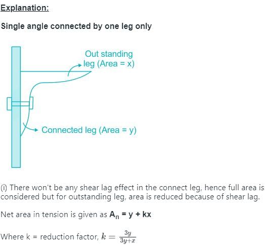
A single angle is connected by one leg only. If the area of outstanding leg is x, net area of connecting leg is y, and k is reduction factor whose value is less than 1, then the net effective area of angle in tension will be:- a)x + y
- b)x + ky
- c)y + kx
- d)k(x + y)
Correct answer is option 'C'. Can you explain this answer?
A single angle is connected by one leg only. If the area of outstanding leg is x, net area of connecting leg is y, and k is reduction factor whose value is less than 1, then the net effective area of angle in tension will be:
a)
x + y
b)
x + ky
c)
y + kx
d)
k(x + y)
|
|
Tanvi Shah answered |
Correct answer is C.
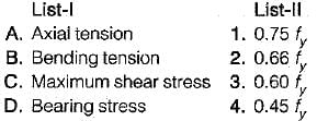
Which one of the following stresses is independent of yield stress as a permissible stress for steel members?- a)Axial tensile stress
- b)Maximum shear stress
- c)Bearing stress
- d)Stress in slab base
Correct answer is option 'D'. Can you explain this answer?
Which one of the following stresses is independent of yield stress as a permissible stress for steel members?
a)
Axial tensile stress
b)
Maximum shear stress
c)
Bearing stress
d)
Stress in slab base
|
|
Neha Mukherjee answered |
Permissible values
Axial tensile stress = 0.6fy
Bearing stress = 0.75fy
Maximum shear stress = 0.45fy
Stress in slab base = 185 MPa for all type of steels.
Axial tensile stress = 0.6fy
Bearing stress = 0.75fy
Maximum shear stress = 0.45fy
Stress in slab base = 185 MPa for all type of steels.
In case of single angles in tension connected by one leg only, the net effective area as per IS : 800 is
Where a is net sectional area of connected leg and b is area of the outstanding leg.- a)gross area-area of holes
- b)

- c)

- d)

Correct answer is option 'B'. Can you explain this answer?
In case of single angles in tension connected by one leg only, the net effective area as per IS : 800 is
Where a is net sectional area of connected leg and b is area of the outstanding leg.
Where a is net sectional area of connected leg and b is area of the outstanding leg.
a)
gross area-area of holes
b)
c)
d)
|
|
Madhurima Banerjee answered |

Failure of tension member is considered when either of following statement is true
1. Excessive elongation in member.
2. Rupture of critical section.
3. Buckling of member.
4. Shear block failure of end connection.- a)1, 2 and 3
- b)2, 3 and 4
- c)1, 3 and 4
- d)1, 2 and 4
Correct answer is option 'D'. Can you explain this answer?
Failure of tension member is considered when either of following statement is true
1. Excessive elongation in member.
2. Rupture of critical section.
3. Buckling of member.
4. Shear block failure of end connection.
1. Excessive elongation in member.
2. Rupture of critical section.
3. Buckling of member.
4. Shear block failure of end connection.
a)
1, 2 and 3
b)
2, 3 and 4
c)
1, 3 and 4
d)
1, 2 and 4
|
|
Sakshi Basak answered |
The three criterion for failure has been considered in new code. Buckling takes place in compression members and not in tension members.
Consider the following statements:
Lug angles are used to
1. increase the lengths of the end connections of angle section.
2. decrease the lengths of the end connections of angle section.
3. increase the lengths of the end connections of channel section.
4. decrease the lengths of the end connections of channel section.Which of these statements are correct?- a)1 and 2
- b)2 and 4
- c)1,3 and 4
- d)1, 2 and 3
Correct answer is option 'B'. Can you explain this answer?
Consider the following statements:
Lug angles are used to
1. increase the lengths of the end connections of angle section.
2. decrease the lengths of the end connections of angle section.
3. increase the lengths of the end connections of channel section.
4. decrease the lengths of the end connections of channel section.
Lug angles are used to
1. increase the lengths of the end connections of angle section.
2. decrease the lengths of the end connections of angle section.
3. increase the lengths of the end connections of channel section.
4. decrease the lengths of the end connections of channel section.
Which of these statements are correct?
a)
1 and 2
b)
2 and 4
c)
1,3 and 4
d)
1, 2 and 3
|
|
Shilpa Pillai answered |
Lug angles are sometimes used to reduce the length of the connections. However their main purpose is to accommodate more number of rivets so that size of the gusset plate may be reduced.
A plate used for connecting two or more structural members intersecting each other is termed as- a)Template
- b)Baseplate
- c)Gusset plate
- d)Shoe plate
Correct answer is option 'C'. Can you explain this answer?
A plate used for connecting two or more structural members intersecting each other is termed as
a)
Template
b)
Baseplate
c)
Gusset plate
d)
Shoe plate
|
|
Samridhi Choudhary answered |
Base plates are provided to distribute the load of a column on greater area.
The capacity of a single ISA 100 x 100 x 10 mm as tension member connected by one leg only using 6 rivets of 20 mm diameter isThe allowable stress is 150 N/mm2- a)333 kN
- b)253 kN
- c)238 kN
- d)210 kN
Correct answer is option 'D'. Can you explain this answer?
The capacity of a single ISA 100 x 100 x 10 mm as tension member connected by one leg only using 6 rivets of 20 mm diameter is
The allowable stress is 150 N/mm2
a)
333 kN
b)
253 kN
c)
238 kN
d)
210 kN

|
Milan Ghosh answered |
Calculation of Capacity of Tension Member Connected by One Leg Only
Given data:
Cross-sectional area (A) of single ISA = 100 x 100 mm
Thickness (t) of single ISA = 10 mm
Diameter (d) of one rivet = 20 mm
Number of rivets (n) = 6
Allowable stress (σallow) = 150 N/mm2
1. Calculation of Net Area (Anet)
The net area of the cross-section after deducting the area of the rivet holes can be calculated as follows:
Area of one rivet hole = π/4 x d2 = π/4 x 202 = 314.16 mm2
Area of six rivet holes = 314.16 x 6 = 1884.96 mm2
Net area (Anet) = A - Area of six rivet holes
Anet = 100 x 100 - 1884.96
Anet = 8115.04 mm2
2. Calculation of Ultimate Load (Pult)
The ultimate load that can be carried by the tension member can be calculated as follows:
Ultimate shear strength of one rivet (Pus) = 0.8 x π/4 x d2 x σallow
Pus = 0.8 x π/4 x 202 x 150
Pus = 9426 N
Ultimate load carried by one rivet (Pur) = Pus x d
Pur = 9426 x 20
Pur = 188520 N
Ultimate load carried by six rivets (Pult) = Pur x n
Pult = 188520 x 6
Pult = 1131120 N
3. Calculation of Capacity of Tension Member (Pcap)
The capacity of the tension member connected by one leg only can be calculated as follows:
Capacity of tension member (Pcap) = 0.75 x Anet x σallow
Pcap = 0.75 x 8115.04 x 150
Pcap = 915352.4 N
4. Comparison of Pult and Pcap
The capacity of the tension member calculated from the net area and allowable stress is less than the ultimate load that can be carried by the six rivets. Hence, the capacity of the tension member is limited by the strength of the rivets.
Final Answer: The capacity of a single ISA 100 x 100 x 10 mm tension member connected by one leg only using 6 rivets of 20 mm diameter is 210 kN.
Consider the following statements regarding tensile test diagrams for carbon steels with varying carbon contents:
As the carbon content increases
1. the ultimate strength of steel decreases
2. the elongation before fracture increases
3. the ductility of the metal decreases
4. the ultimate strength increasesWhich of these statements are correct?- a)3 and 4
- b)1 and 3
- c)1,2 and 3
- d)1 and 2
Correct answer is option 'A'. Can you explain this answer?
Consider the following statements regarding tensile test diagrams for carbon steels with varying carbon contents:
As the carbon content increases
1. the ultimate strength of steel decreases
2. the elongation before fracture increases
3. the ductility of the metal decreases
4. the ultimate strength increases
As the carbon content increases
1. the ultimate strength of steel decreases
2. the elongation before fracture increases
3. the ductility of the metal decreases
4. the ultimate strength increases
Which of these statements are correct?
a)
3 and 4
b)
1 and 3
c)
1,2 and 3
d)
1 and 2
|
|
Shraddha Datta answered |
Explanation:
Tensile test diagrams are used to characterize the mechanical properties of materials, including carbon steels. These diagrams provide information about the relationship between stress and strain, and can help determine the ultimate strength, elongation before fracture, and ductility of the material.
Statement 1: As the carbon content increases, the ultimate strength of steel decreases.
This statement is incorrect. In fact, as the carbon content increases in carbon steels, the ultimate strength also increases. This is because carbon is a strong and hardening element in steel. It forms carbides, which contribute to the strength and hardness of the steel. Therefore, higher carbon content generally results in higher ultimate strength.
Statement 2: As the carbon content increases, the elongation before fracture increases.
This statement is incorrect. As the carbon content increases in carbon steels, the elongation before fracture typically decreases. Carbon steels with higher carbon contents tend to be more brittle and have lower ductility, which means they are more prone to fracture without significant elongation.
Statement 3: As the carbon content increases, the ductility of the metal decreases.
This statement is correct. As mentioned earlier, carbon steels with higher carbon contents are generally more brittle and have lower ductility. Ductility refers to the ability of a material to deform plastically before fracturing. Higher carbon content reduces the ability of the steel to deform plastically, making it less ductile.
Statement 4: As the carbon content increases, the ultimate strength increases.
This statement is correct. As mentioned earlier, higher carbon content in carbon steels generally leads to higher ultimate strength. Carbon is a strong and hardening element in steel, and its presence contributes to the strength and hardness of the material.
Conclusion:
Based on the explanations above, the correct statements regarding tensile test diagrams for carbon steels with varying carbon contents are:
1. As the carbon content increases, the ductility of the metal decreases.
2. As the carbon content increases, the ultimate strength increases.
Therefore, the correct answer is option A: 3 and 4.
The order of elongation which a specimen of mild steel undergoes before fracture is- a)0.1%
- b)1%
- c)10%
- d)100%
Correct answer is option 'C'. Can you explain this answer?
The order of elongation which a specimen of mild steel undergoes before fracture is
a)
0.1%
b)
1%
c)
10%
d)
100%
|
|
Hiral Sharma answered |
For mild steel
(i) Proportional limit (190 - 220) N/mm2
(ii) Yield strength (230 - 250) N/mm2
(iii) Ultimate strength (410 - 530) N/mm2
(iv) Fracture strength (250 - 300) N/mm2
(v) Elongation at fracture (23 - 35)% Thus the order of elongation is 10%
(i) Proportional limit (190 - 220) N/mm2
(ii) Yield strength (230 - 250) N/mm2
(iii) Ultimate strength (410 - 530) N/mm2
(iv) Fracture strength (250 - 300) N/mm2
(v) Elongation at fracture (23 - 35)% Thus the order of elongation is 10%
An equal angle of area A has been attached to the support by means of a lug angle. If allowable stress in tension is f, what is the load carrying capacity of the member?- a)0.5fA
- b)0.85fA
- c)0.9fA
- d)1.0fA
Correct answer is option 'D'. Can you explain this answer?
An equal angle of area A has been attached to the support by means of a lug angle. If allowable stress in tension is f, what is the load carrying capacity of the member?
a)
0.5fA
b)
0.85fA
c)
0.9fA
d)
1.0fA
|
|
Pankaj Kapoor answered |
Strength of member = allowable tensile stress x
Net area of the angle
Net area = Gross Area - deduction for holes.
Net area of the angle
Net area = Gross Area - deduction for holes.
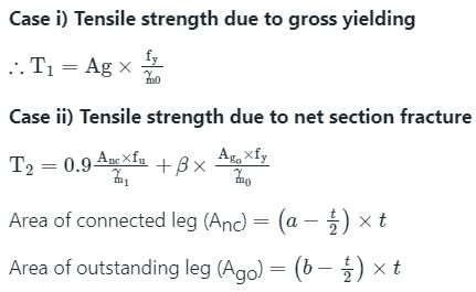
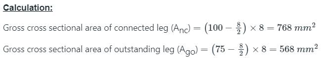
A tie member consists of ISA 100 × 75 × 8 longer leg is connected to a gusset plate. The gross cross sectional area of connected and unconnected leg are _______ mm2 respectively.- a)768 and 568
- b)344 and 288
- c)976 and 654
- d)1206 and 743
Correct answer is option 'A'. Can you explain this answer?
A tie member consists of ISA 100 × 75 × 8 longer leg is connected to a gusset plate. The gross cross sectional area of connected and unconnected leg are _______ mm2 respectively.
a)
768 and 568
b)
344 and 288
c)
976 and 654
d)
1206 and 743

|
Telecom Tuners answered |
In a tension member if one or more than one rivet hole are off the line, the failure of the member depends upon- a)pitch
- b)gauge
- c)diameter of the rivet holes
- d)All of the above
Correct answer is option 'D'. Can you explain this answer?
In a tension member if one or more than one rivet hole are off the line, the failure of the member depends upon
a)
pitch
b)
gauge
c)
diameter of the rivet holes
d)
All of the above
|
|
Samridhi Choudhary answered |
In a tension member, if one or more than one rivet hole are off the line, the failure of the member depends upon the pitch, gauge, and diameter of the rivet holes. This means that all of the options mentioned - pitch, gauge, and diameter of the rivet holes - are correct.
Let's understand why this is the case:
1. Pitch: The pitch refers to the distance between the centers of adjacent rivet holes along the length of the member. When a rivet hole is off the line, it affects the pitch. If the pitch is not maintained properly, it can lead to uneven distribution of load and stress concentrations. This can weaken the member and result in failure.
2. Gauge: The gauge refers to the distance between the centers of rivet holes in the transverse direction of the member. Similar to the pitch, if the gauge is not maintained properly due to off-line rivet holes, it can lead to uneven distribution of load and stress concentrations. This can also weaken the member and result in failure.
3. Diameter of the rivet holes: The diameter of the rivet holes is also important for the strength of the tension member. If the rivet holes are not drilled properly or if their diameter is not appropriate, it can affect the fit and strength of the rivets. This can lead to reduced load-carrying capacity and potential failure of the member.
All of these factors - pitch, gauge, and diameter of the rivet holes - are interrelated and contribute to the overall strength and integrity of the tension member. If any of them are compromised due to off-line rivet holes, it can significantly reduce the member's ability to withstand tension forces and result in failure.
Therefore, it is crucial to ensure that all rivet holes are drilled accurately and are in line to maintain the required pitch, gauge, and diameter for a tension member to perform effectively and safely.
The effective flange area in tension of a piate girder is equal towhere Af is the area of each flange and Aw is the web area.- a)Af
- b)

- c)

- d)

Correct answer is option 'D'. Can you explain this answer?
The effective flange area in tension of a piate girder is equal to
where Af is the area of each flange and Aw is the web area.
a)
Af
b)
c)
d)
|
|
Maulik Das answered |
Effective flange area = 
Net area of the flange =
Net area of the flange =
Tacking rivets in tension members, are provided at a pitch in line not exceeding- a)25 cm
- b)50 cm
- c)60 cm
- d)100 cm
Correct answer is option 'D'. Can you explain this answer?
Tacking rivets in tension members, are provided at a pitch in line not exceeding
a)
25 cm
b)
50 cm
c)
60 cm
d)
100 cm
|
|
Anuj Chakraborty answered |
Tacking Rivets in Tension Members
Tacking rivets are temporary fasteners used during the fabrication of tension members to hold the components in place until the final riveting or welding is completed. The pitch of these tacking rivets is important to ensure the strength and stability of the final structure.
Pitch of Tacking Rivets
The pitch of tacking rivets in tension members should be in line and not exceed 100 cm. This means that the distance between two consecutive tacking rivets should not be more than 100 cm.
Reason for the Pitch Limit
The pitch limit for tacking rivets is set to ensure that the tension member remains stable during the fabrication process. If the pitch is too wide, there is a risk of the components shifting or twisting, which can result in a weaker final structure.
The pitch limit also ensures that the tacking rivets do not interfere with the final riveting or welding. If the pitch is too narrow, it can be difficult to remove the tacking rivets without damaging the final structure.
Conclusion
In summary, tacking rivets are important temporary fasteners used during the fabrication of tension members. The pitch of these rivets should be in line and not exceed 100 cm to ensure stability and strength of the final structure.

For a single section used as a tension member, the given area is assumed- a)20% to 30% in excess of the net area
- b)30% to 40% in excess of the net area
- c)40% to 50% in excess of the net area
- d)50% to 60% in excess of the net area
Correct answer is option 'A'. Can you explain this answer?
For a single section used as a tension member, the given area is assumed
a)
20% to 30% in excess of the net area
b)
30% to 40% in excess of the net area
c)
40% to 50% in excess of the net area
d)
50% to 60% in excess of the net area
|
|
Gitanjali Menon answered |
Explanation:
In tension members, the net area is the effective area available for resisting the tensile force. The net area is obtained by deducting the holes, fasteners or any other discontinuities from the gross area of the section. However, due to the presence of stress concentrations at the ends of the fastener holes, the actual stress in the member is higher than the nominal stress based on the net area.
To account for this, a reduction factor is applied to the nominal stress based on the net area, known as the fillet weld or fastener strength reduction factor (phi). This factor is typically 0.75 for bolts and 0.70 for welds.
To ensure that the actual stress in the member does not exceed the yield strength, the area of the section is increased by a certain percentage over the net area. This excess area is known as the gross area and is used to calculate the nominal stress based on the applied load.
For a single section used as a tension member, the given area is assumed to be 20% to 30% in excess of the net area. This means that the gross area is 20% to 30% larger than the net area. The exact value depends on the type of connection used and the size of the section.
The purpose of this excess area is to ensure that the actual stress in the member does not exceed the yield strength and to provide some margin of safety against unexpected loads or flaws in the material.
Therefore, the correct answer is option 'A'.
For double angles carrying tension placed back to back and connected to either side of the gusset plate, the sectional area of the section, is equal to gross sectional area of- a)section
- b)section plus area of rivet holes
- c)section minus area of rivet holes
- d)section multiplied by the area of the rivet hole
Correct answer is option 'C'. Can you explain this answer?
For double angles carrying tension placed back to back and connected to either side of the gusset plate, the sectional area of the section, is equal to gross sectional area of
a)
section
b)
section plus area of rivet holes
c)
section minus area of rivet holes
d)
section multiplied by the area of the rivet hole
|
|
Pallabi Chavan answered |
Explanation:
When double angles are used to carry tension, they are usually placed back to back and connected to either side of a gusset plate. In this configuration, the sectional area of the section is equal to the gross sectional area of the section minus the area of the rivet holes.
Sectional Area
The sectional area refers to the cross-sectional area of the double angles. It is calculated by multiplying the thickness of the angles by the width of the angles.
Gross Sectional Area
The gross sectional area refers to the total cross-sectional area of the double angles, including the area occupied by the rivet holes.
Rivet Holes
Rivet holes are drilled in the double angles to allow for the connection of the angles to the gusset plate. These holes reduce the net sectional area of the angles.
Calculation
To calculate the net sectional area, we subtract the area of the rivet holes from the gross sectional area.
Net Sectional Area = Gross Sectional Area - Area of Rivet Holes
The correct answer is option 'C' because the sectional area of the section is equal to the gross sectional area minus the area of the rivet holes.
This is an important consideration in the design of connections using double angles. The net sectional area determines the strength of the connection and must be sufficient to resist the applied tension.
It is worth noting that the area of the rivet holes can be significant, especially if the number of rivets is large or if the rivet size is large. Therefore, it is important to consider the area of the rivet holes when calculating the net sectional area.
Chapter doubts & questions for Tension Members - Design of Steel Structures 2025 is part of Civil Engineering (CE) exam preparation. The chapters have been prepared according to the Civil Engineering (CE) exam syllabus. The Chapter doubts & questions, notes, tests & MCQs are made for Civil Engineering (CE) 2025 Exam. Find important definitions, questions, notes, meanings, examples, exercises, MCQs and online tests here.
Chapter doubts & questions of Tension Members - Design of Steel Structures in English & Hindi are available as part of Civil Engineering (CE) exam.
Download more important topics, notes, lectures and mock test series for Civil Engineering (CE) Exam by signing up for free.
Design of Steel Structures
10 videos|41 docs|17 tests
|
|
© EduRev
|
Education Revolution
|


|


Signup to see your scores
go up within 7 days!
Access 1000+ FREE Docs, Videos and Tests
Takes less than 10 seconds to signup