


All Exams >
Mechanical Engineering >
Topicwise Question Bank for Mechanical Engineering >
All Questions
All questions of Power Plant Engineering for Mechanical Engineering Exam
Which one of the following is afire tube boiler?- a)Babcock-Wiicox boiler
- b)Locomotive boiler
- c)Stirling boiler
- d)Benson boiler
Correct answer is option 'B'. Can you explain this answer?
Which one of the following is afire tube boiler?
a)
Babcock-Wiicox boiler
b)
Locomotive boiler
c)
Stirling boiler
d)
Benson boiler

|
Gattu Yashwanth Sai answered |
Fire tube boilers are generally used in locomotives like trains so they are also called as locomotive boiler

Which one of the following forms of draft tube will not improve the hydraulic efficiency of the turbine?- a)straight cylindrical
- b)conical type
- c)bell-mouthed
- d)bent tube
Correct answer is option 'A'. Can you explain this answer?
Which one of the following forms of draft tube will not improve the hydraulic efficiency of the turbine?
a)
straight cylindrical
b)
conical type
c)
bell-mouthed
d)
bent tube
|
|
Neha Joshi answered |
Purpose of draft tube is to convert kinetic energy into pressure energy, so option (a) wiil not be suitable for the intended purpose of draft tube.
If x1 and x2 be the dryness fractions obtained in separating calorimeter and throttling calorimeter respectively, then the actual dryness friction of steam will be- a)x1 + x2
- b)

- c)x1x2
- d)

Correct answer is option 'C'. Can you explain this answer?
If x1 and x2 be the dryness fractions obtained in separating calorimeter and throttling calorimeter respectively, then the actual dryness friction of steam will be
a)
x1 + x2
b)
c)
x1x2
d)
|
|
Nishanth Basu answered |
For the combined throttling separating calorimeter, if x1 is the dryness fraction obtained in separating colorimeter and x2 is the dryness fraction obtained in throttling calorimeter then the actual dryness fraction
x = x1x2
x = x1x2
Regulation of a pelton turbine is done by changing- a)the head available at the nozzle
- b)the annular area of the nozzle
- c)the velocity of flow from the nozzle
- d)the length of the nozzle
Correct answer is option 'B'. Can you explain this answer?
Regulation of a pelton turbine is done by changing
a)
the head available at the nozzle
b)
the annular area of the nozzle
c)
the velocity of flow from the nozzle
d)
the length of the nozzle
|
|
Saranya Saha answered |
A spear or needle is so arranged that it can move forward or backward thereby decreasing or increasing the annular area of the nozzle passage. This spear nozzle regulates the water flow through the nozzle.
In a gas turbine cycle, the turbine output is 800 kj/kg, the compressor work is 500 kj/kg and the heat supplied is 1200 kj/kg. The thermal efficiency of the cycle is- a)15%
- b)25%
- c)30%
- d)35%
Correct answer is option 'B'. Can you explain this answer?
In a gas turbine cycle, the turbine output is 800 kj/kg, the compressor work is 500 kj/kg and the heat supplied is 1200 kj/kg. The thermal efficiency of the cycle is
a)
15%
b)
25%
c)
30%
d)
35%
|
|
Mehul Yadav answered |
Network = WT- WC
= 800 - 500 = 300 kJ/kg
Heat supplied = 1200 kJ/kg
Thermal efficiency = Network/Heat applied
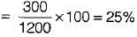
= 800 - 500 = 300 kJ/kg
Heat supplied = 1200 kJ/kg
Thermal efficiency = Network/Heat applied
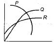
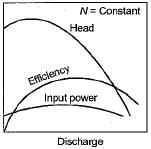
The characteristics of a pump are as shown in the given figure. Based on this figure, match List-I with List-II choose the correct answer using the codes given below the list:
List - I
A. Curve P
B. Curve Q
C. Curve R
List - II
1. Discharge versus head
2. Head versus discharge
3. Power versus discharge
4. Efficiency versus discharge
Codes
A B C
(a) 2 4 3
(b) 1 3 2
(c) 1 4 3
(d) 4 3 1- a)(a)
- b)(b)
- c)(c)
- d)(d)
Correct answer is option 'A'. Can you explain this answer?
The characteristics of a pump are as shown in the given figure. Based on this figure, match List-I with List-II choose the correct answer using the codes given below the list:
List - I
A. Curve P
B. Curve Q
C. Curve R
List - II
1. Discharge versus head
2. Head versus discharge
3. Power versus discharge
4. Efficiency versus discharge
Codes
A B C
(a) 2 4 3
(b) 1 3 2
(c) 1 4 3
(d) 4 3 1
List - I
A. Curve P
B. Curve Q
C. Curve R
List - II
1. Discharge versus head
2. Head versus discharge
3. Power versus discharge
4. Efficiency versus discharge
Codes
A B C
(a) 2 4 3
(b) 1 3 2
(c) 1 4 3
(d) 4 3 1
a)
(a)
b)
(b)
c)
(c)
d)
(d)
|
|
Rhea Reddy answered |
Operating characteristic curve of a centrifugal pump.
Water is to be lifted by a net head of 184 m. Identical pumps with specific speed of 30 and rotative of 1500 rpm capable of discharging 200 L/s are available. The number of pumps required is [Take 1843/4 = 50]- a)5
- b)2
- c)3
- d)4
Correct answer is option 'A'. Can you explain this answer?
Water is to be lifted by a net head of 184 m. Identical pumps with specific speed of 30 and rotative of 1500 rpm capable of discharging 200 L/s are available. The number of pumps required is [Take 1843/4 = 50]
a)
5
b)
2
c)
3
d)
4
|
|
Yash Das answered |
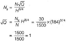
∴ Q = 1000 L/s
Number of pumps = 1000/200 = 5
For starting an axial flow pump, its delivery valve should be- a)closed
- b)partially open
- c)open
- d)either open or closed
Correct answer is option 'C'. Can you explain this answer?
For starting an axial flow pump, its delivery valve should be
a)
closed
b)
partially open
c)
open
d)
either open or closed

|
Anshul Chakraborty answered |
Explanation:
Importance of delivery valve in starting an axial flow pump:
The delivery valve in an axial flow pump is responsible for controlling the flow of fluid from the pump to the piping system. It plays a crucial role in the startup process of the pump.
Reason for keeping the delivery valve open:
- When starting an axial flow pump, the delivery valve should be kept open to allow the fluid to flow freely through the pump and into the piping system.
- Keeping the delivery valve open ensures that there is no obstruction to the flow of fluid, allowing the pump to operate efficiently.
Consequences of closing the delivery valve:
- If the delivery valve is closed during the startup process, it can lead to increased pressure within the pump, causing damage to the pump components.
- Closing the delivery valve can also result in cavitation, which can further damage the pump and reduce its efficiency.
Conclusion:
In conclusion, it is important to keep the delivery valve of an axial flow pump open when starting the pump. This ensures smooth flow of fluid and prevents any damage to the pump components.
The function of an economizer in a steam power plant is to- a)increase the temperature of air supplied to a boiler
- b)increase the enthalpy of feed water
- c)condense the exhaust steam from the turbine
- d)heat the fuel before combustion
Correct answer is option 'B'. Can you explain this answer?
The function of an economizer in a steam power plant is to
a)
increase the temperature of air supplied to a boiler
b)
increase the enthalpy of feed water
c)
condense the exhaust steam from the turbine
d)
heat the fuel before combustion

|
Pallabi Chavan answered |
An economizer is a device used to heat feed water by utilizing the heat in the exhaust Flue gases before leaving through the chimney, i.e., to increase the enthalpy of feed water.
Consider the following statements regarding air vessels provided in reciprocating pump installations
1. The air vessels are fitted both on suction and delivery sides
2. The air vessels are fitted for from the pump cylinder
3. The air vessels save energy by reducing the friction lossQ. Which of these statements are correct?- a)1, 2 and 3
- b)1 and 2
- c)2 and 3
- d)1 and 3
Correct answer is option 'D'. Can you explain this answer?
Consider the following statements regarding air vessels provided in reciprocating pump installations
1. The air vessels are fitted both on suction and delivery sides
2. The air vessels are fitted for from the pump cylinder
3. The air vessels save energy by reducing the friction loss
1. The air vessels are fitted both on suction and delivery sides
2. The air vessels are fitted for from the pump cylinder
3. The air vessels save energy by reducing the friction loss
Q. Which of these statements are correct?
a)
1, 2 and 3
b)
1 and 2
c)
2 and 3
d)
1 and 3
|
|
Maulik Joshi answered |
An air vessel is a close chamber having an opening at its base through which the liquid may flow into the vessel or it may flow out from the vessel air vessel fitted to suction and delivery pipes of a single-acting pump. The air vessel fulfill following functions.
(i) It continuous supply of provides liquid at a uniform rate.
(ii) It saves considerable amount of work in overcoming the frictional resistance in suction and delivery pipes.
(iii) It facilitates pump to run at a high speed without separation.
(i) It continuous supply of provides liquid at a uniform rate.
(ii) It saves considerable amount of work in overcoming the frictional resistance in suction and delivery pipes.
(iii) It facilitates pump to run at a high speed without separation.
A pump running at 1000 rpm consumes 1 kW and generates head of 10 m of water. When it is operated at 2000 rpm. Its power consumption and head generated would be- a)4 kW, 50 m of water
- b)6 kW, 20 m of water
- c)3 kW, 30 m of water
- d)8 kW, 40 m of water
Correct answer is option 'D'. Can you explain this answer?
A pump running at 1000 rpm consumes 1 kW and generates head of 10 m of water. When it is operated at 2000 rpm. Its power consumption and head generated would be
a)
4 kW, 50 m of water
b)
6 kW, 20 m of water
c)
3 kW, 30 m of water
d)
8 kW, 40 m of water
|
|
Arshiya Roy answered |
Given Data:
- Pump speed at 1000 rpm: Power = 1 kW, Head = 10 m
- Pump speed at 2000 rpm: ?
Calculation:
- Power Consumption (P) is directly proportional to the cube of the speed (N) of the pump. The formula is P2/P1 = (N2/N1)^3
- Power at 2000 rpm = (2000/1000)^3 * 1 kW = 8 kW
- Head generated by the pump is directly proportional to the square of the speed of the pump. The formula is H2/H1 = (N2/N1)^2
- Head at 2000 rpm = (2000/1000)^2 * 10 m = 40 m
Therefore, when the pump is operated at 2000 rpm, the power consumption would be 8 kW and the head generated would be 40 m of water, which corresponds to option 'D'.
Select the most appropriate pump from Group-2 to handle each fluid flow given in Group-1.
Group - 1
P. Highly viscous fluid flow
Q. Fluid containing large amount of abrasive solid
Group - 2
1. Piston pump
2. Gear pump
3. Plunger pump
4. Centrifugal pump- a)P - (2), Q - (1)
- b)P - (2), Q - (4)
- c)P - (3), Q - (4)
- d)P - (4),Q - (3)
Correct answer is option 'B'. Can you explain this answer?
Select the most appropriate pump from Group-2 to handle each fluid flow given in Group-1.
Group - 1
P. Highly viscous fluid flow
Q. Fluid containing large amount of abrasive solid
Group - 2
1. Piston pump
2. Gear pump
3. Plunger pump
4. Centrifugal pump
Group - 1
P. Highly viscous fluid flow
Q. Fluid containing large amount of abrasive solid
Group - 2
1. Piston pump
2. Gear pump
3. Plunger pump
4. Centrifugal pump
a)
P - (2), Q - (1)
b)
P - (2), Q - (4)
c)
P - (3), Q - (4)
d)
P - (4),Q - (3)
|
|
Shounak Saini answered |
Piston pump will not handle corrosive liquids and slurries containing abrasive solids, since damage is done to the valves and the machined surfaces of the cylinder and piston. Centrifugal pumps are widely unused in the chemical industry because they can be constructed to handle corrosive liquids and suspensions.
Which one of the following additions/sets of additions simple gas turbine cycle will have NO effect on the power output the cycle?- a)Regeneration
- b)Intercooling and regeneration
- c)Reheating and intercooling
- d)Reheating, intercooling and regeneration
Correct answer is option 'A'. Can you explain this answer?
Which one of the following additions/sets of additions simple gas turbine cycle will have NO effect on the power output the cycle?
a)
Regeneration
b)
Intercooling and regeneration
c)
Reheating and intercooling
d)
Reheating, intercooling and regeneration
|
|
Divya Kulkarni answered |
Since the exhaust gases of the gas turbine having very high pressure and temperature, these gases are used to heat the air before going to the combustion chamber of gas turbine which reduces the overall heat addition in the combustion chamber, But workout put will be same as without regeneration.
In a centrifugal compressor, the pressure rise per stage is restricted to- a)3 : 2
- b)2 : 1
- c)3 : 1
- d)4 : 1
Correct answer is option 'D'. Can you explain this answer?
In a centrifugal compressor, the pressure rise per stage is restricted to
a)
3 : 2
b)
2 : 1
c)
3 : 1
d)
4 : 1
|
|
Nishanth Banerjee answered |
Pressure Rise per Stage in Centrifugal Compressor
Pressure rise per stage in a centrifugal compressor is restricted to a ratio of 4:1. This means that for every stage in the compressor, the pressure is increased by a factor of 4.
Explanation:
Centrifugal Compressor Stages
- A centrifugal compressor typically consists of multiple stages, each designed to increase the pressure of the gas being compressed.
- The pressure rise per stage is limited in order to prevent excessive temperature rise and to maintain efficiency.
Pressure Ratio of 4:1
- The 4:1 pressure rise per stage ratio is a common design parameter for centrifugal compressors.
- This ratio allows for efficient compression of the gas while preventing excessive temperature rise, which could lead to issues such as compressor surge.
Importance of Pressure Ratio Limitation
- By restricting the pressure rise per stage to 4:1, the compressor can effectively handle the compression process without compromising performance or reliability.
- This limitation also helps in achieving the desired compression ratio across multiple stages of the compressor.
Conclusion:
In a centrifugal compressor, the pressure rise per stage is restricted to a ratio of 4:1 to ensure efficient compression of the gas while maintaining performance and reliability.
At which location of a converging-diverging nozzle, does the shock-boundary layer interaction take place- a)converging portion
- b)throat
- c)inlet
- d)diverging portion
Correct answer is option 'D'. Can you explain this answer?
At which location of a converging-diverging nozzle, does the shock-boundary layer interaction take place
a)
converging portion
b)
throat
c)
inlet
d)
diverging portion
|
|
Sreemoyee Chauhan answered |
At the diverging section of converging diverging nozzle flow velocities are very-very high (M > 1) due to this shock is observed at the diverging portion.
Which one of the following type of compressor is mostly used for supercharging of I.C. engine- a)radial flow compressor
- b)axial flow compressor
- c)root blower
- d)reciprocating compressor
Correct answer is option 'C'. Can you explain this answer?
Which one of the following type of compressor is mostly used for supercharging of I.C. engine
a)
radial flow compressor
b)
axial flow compressor
c)
root blower
d)
reciprocating compressor
|
|
Megha Choudhury answered |
Since very small pressure ratio is required in supercharging of I.C. engine root blower or centrifugal compressor is used.

A gas turbine operates between 50C and 8390C. What is the pressure ratio at which cycle efficiency equals carnot cycle efficiency?- a)16
- b)4
- c)128
- d)112
Correct answer is option 'C'. Can you explain this answer?
A gas turbine operates between 50C and 8390C. What is the pressure ratio at which cycle efficiency equals carnot cycle efficiency?
a)
16
b)
4
c)
128
d)
112
|
|
Nandini Basak answered |
Given: Temperature at which gas turbine operates, T1 = 50°C and T3 = 8390°C
To find: Pressure ratio at which cycle efficiency equals Carnot cycle efficiency
Concepts used: Brayton cycle, Carnot cycle
Explanation:
- The Brayton cycle is the ideal cycle for gas turbine engines. It consists of four processes: isentropic compression, constant pressure heat addition, isentropic expansion, and constant pressure heat rejection. The cycle is shown below:

- The efficiency of the Brayton cycle is given by:
ηBrayton = 1 - (1/r)^(γ-1)
where r is the pressure ratio and γ is the specific heat ratio.
- The Carnot cycle is the ideal cycle for heat engines. It consists of four processes: isothermal heat addition, adiabatic expansion, isothermal heat rejection, and adiabatic compression. The cycle is shown below:

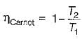
- The efficiency of the Carnot cycle is given by:
ηCarnot = 1 - T1/T3
where T1 is the temperature at which heat is added and T3 is the temperature at which heat is rejected.
- To find the pressure ratio at which cycle efficiency equals Carnot cycle efficiency, we need to equate the two efficiencies and solve for r:
1 - (1/r)^(γ-1) = 1 - T1/T3
(1/r)^(γ-1) = T1/T3
r = (T3/T1)^(1/(γ-1))
- Substituting the given values, we get:
r = (8390+273)/(50+273)^(1.4-1) = 128
Therefore, the pressure ratio at which cycle efficiency equals Carnot cycle efficiency is 128. Answer: (c)
To find: Pressure ratio at which cycle efficiency equals Carnot cycle efficiency
Concepts used: Brayton cycle, Carnot cycle
Explanation:
- The Brayton cycle is the ideal cycle for gas turbine engines. It consists of four processes: isentropic compression, constant pressure heat addition, isentropic expansion, and constant pressure heat rejection. The cycle is shown below:

- The efficiency of the Brayton cycle is given by:
ηBrayton = 1 - (1/r)^(γ-1)
where r is the pressure ratio and γ is the specific heat ratio.
- The Carnot cycle is the ideal cycle for heat engines. It consists of four processes: isothermal heat addition, adiabatic expansion, isothermal heat rejection, and adiabatic compression. The cycle is shown below:

- The efficiency of the Carnot cycle is given by:
ηCarnot = 1 - T1/T3
where T1 is the temperature at which heat is added and T3 is the temperature at which heat is rejected.
- To find the pressure ratio at which cycle efficiency equals Carnot cycle efficiency, we need to equate the two efficiencies and solve for r:
1 - (1/r)^(γ-1) = 1 - T1/T3
(1/r)^(γ-1) = T1/T3
r = (T3/T1)^(1/(γ-1))
- Substituting the given values, we get:
r = (8390+273)/(50+273)^(1.4-1) = 128
Therefore, the pressure ratio at which cycle efficiency equals Carnot cycle efficiency is 128. Answer: (c)
Consider an actual regenerative Rankine cycle with one open feed water heater. For each kg steam entering the turbine, if m kg steam with a specific enthalpy of h1 is bleed from the turbine, and the specific enthalpy of liquid water entering the heater is h2, then h3 specific enthalpy of saturated liquid leaving the heater is equal to- a)mh1 - (h2 - h1)
- b)h1 - m(h2 - h1)
- c)h2 - m(h2 - h1)
- d)mh2 - (h2 - h1)
Correct answer is option 'C'. Can you explain this answer?
Consider an actual regenerative Rankine cycle with one open feed water heater. For each kg steam entering the turbine, if m kg steam with a specific enthalpy of h1 is bleed from the turbine, and the specific enthalpy of liquid water entering the heater is h2, then h3 specific enthalpy of saturated liquid leaving the heater is equal to
a)
mh1 - (h2 - h1)
b)
h1 - m(h2 - h1)
c)
h2 - m(h2 - h1)
d)
mh2 - (h2 - h1)
|
|
Sakshi Basak answered |
By analyzing input and output energy on open feed water heater, we get
h3 = mh1 + (1 - m)h2 = mh1 + h2- mh2
h3 = h2 - m (h2 - h1)
h3 = mh1 + (1 - m)h2 = mh1 + h2- mh2
h3 = h2 - m (h2 - h1)
Rotary compressor is best suited for- a)large quantity of air at low pressure ratio
- b)large quantity of air at high pressure ratio
- c)small quantity of air at high pressure ratio
- d)small quantity of air at low pressure ratio
Correct answer is option 'A'. Can you explain this answer?
Rotary compressor is best suited for
a)
large quantity of air at low pressure ratio
b)
large quantity of air at high pressure ratio
c)
small quantity of air at high pressure ratio
d)
small quantity of air at low pressure ratio
|
|
Siddharth Datta answered |
Rotary compressor is suitable for low pressure ratio and large quantity of air.
In a regenerative feed heating cycle, the greatest economy is affected when steam is extracted- a)from only one suitable point of steam turbine
- b)from several places in different stages of steam turbine
- c)only from the last stage of steam turbine
- d)only from the first stage of steam turbine
Correct answer is option 'B'. Can you explain this answer?
In a regenerative feed heating cycle, the greatest economy is affected when steam is extracted
a)
from only one suitable point of steam turbine
b)
from several places in different stages of steam turbine
c)
only from the last stage of steam turbine
d)
only from the first stage of steam turbine
|
|
Sinjini Bose answered |
Due to steam extraction at several places:
- Loss of work output increases
- Steam rate increase which requires bigger boiler size
- Loss of work output increases
- Steam rate increase which requires bigger boiler size
In a reaction turbine, a stage is represented by- a)each row of blades
- b)number of exits of steam .
- c)number of bleeding
- d)none of these
Correct answer is option 'A'. Can you explain this answer?
In a reaction turbine, a stage is represented by
a)
each row of blades
b)
number of exits of steam .
c)
number of bleeding
d)
none of these
|
|
Kirti Sharma answered |
In a reaction turbine, a stage is represented by:
A stage in a reaction turbine refers to each row of blades that the steam passes through as it flows through the turbine. It is an important concept in understanding the operation and design of reaction turbines.
Explanation:
A reaction turbine is a type of turbine where the steam expands and changes direction as it passes through the blades. It is a continuous-flow machine, meaning that steam enters the turbine at one end and exits at the other, while the blades extract energy from the steam. The steam pressure decreases gradually as it passes through each stage, and the velocity of the steam increases.
Each row of blades:
- In a reaction turbine, the blades are arranged in multiple rows, which are referred to as stages.
- Each stage consists of a set of stationary blades (nozzles or guides) and a set of rotating blades (buckets or rotor blades).
- The steam passes through each stage, and as it does so, it undergoes a change in pressure and velocity, transferring energy to the blades and causing the rotor to rotate.
Number of exits of steam:
- The number of exits of steam does not represent a stage in a reaction turbine.
- In a reaction turbine, there is typically only one exit for the steam, which is at the exhaust end of the turbine.
- The steam flows through multiple stages, but it is a continuous flow, and there is no separate exit for each stage.
Number of bleeding:
- Bleeding refers to the extraction of steam from an intermediate stage of the turbine to be used for other purposes, such as heating or feedwater heating.
- Bleeding does not represent a stage in a reaction turbine.
- It is a separate feature that can be added to the turbine design, but it does not define a stage.
Conclusion:
In a reaction turbine, a stage is represented by each row of blades. The steam passes through multiple stages, with each stage consisting of a row of stationary blades and a row of rotating blades. The concept of stages is important for understanding the flow of steam and the extraction of energy in a reaction turbine.
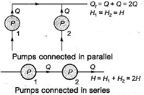
If two pumps identical in all respects and each capable of delivering a discharge Q against a head H are connected in series, the resulting discharge is- a)2Q against a head 2H
- b)2Q against a head H
- c)Q against a head 2H
- d)√Q against a head √2H
Correct answer is option 'C'. Can you explain this answer?
If two pumps identical in all respects and each capable of delivering a discharge Q against a head H are connected in series, the resulting discharge is
a)
2Q against a head 2H
b)
2Q against a head H
c)
Q against a head 2H
d)
√Q against a head √2H
|
|
Neha Joshi answered |
Degree of reaction in an axial flow compressor is defined as the ratio of static enthalpy rise in the- a)rotor to static enthalpy rise in the stator
- b)stator to static enthalpy rise in the rotor
- c)rotor to static enthalpy rise in the stage
- d)stator to static enthalpy rise in the stage
Correct answer is option 'C'. Can you explain this answer?
Degree of reaction in an axial flow compressor is defined as the ratio of static enthalpy rise in the
a)
rotor to static enthalpy rise in the stator
b)
stator to static enthalpy rise in the rotor
c)
rotor to static enthalpy rise in the stage
d)
stator to static enthalpy rise in the stage
|
|
Harshad Iyer answered |
Degree of reaction is the ratio of static enthalpy rise in rotor to static enthalpy rise in the stage.
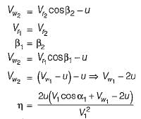
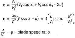
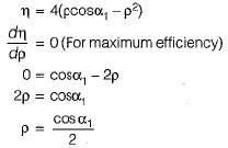
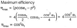
Maximum efficiency of a De-Laval turbine is
where α = Nozzle angle- a)sin2α
- b)cos2α
- c)tan2α
- d)cot2α
Correct answer is option 'B'. Can you explain this answer?
Maximum efficiency of a De-Laval turbine is
where α = Nozzle angle
where α = Nozzle angle
a)
sin2α
b)
cos2α
c)
tan2α
d)
cot2α
|
|
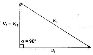
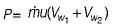
Bibek Mehra answered |
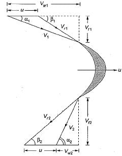
Power developed by the Runner
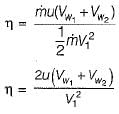
Blade efficiency =
For maximum efficiency of impulse turbine.
It is assumed that friction on the turbine blade is neglected i.e.,
 and blade is symmetrical i.e., β1 = β2 from the velocity triangle
Vw1 =V1cosα1
For critical pressure ratio, what is the discharge through a nozzle?- a)maximum
- b)minimum
- c)zero
- d)cannot be predicted without knowing other parameters
Correct answer is option 'A'. Can you explain this answer?
For critical pressure ratio, what is the discharge through a nozzle?
a)
maximum
b)
minimum
c)
zero
d)
cannot be predicted without knowing other parameters
|
|
Devansh Banerjee answered |
At critical pressure ratio the discharge becomes maximum and after that the discharge remains constant irrespective of any decrease in pressure ratio.
Efficiency of chimney draught is of the order of- a)8-10%
- b)5-6%
- c)2-3%
- d)<1%
Correct answer is option 'D'. Can you explain this answer?
Efficiency of chimney draught is of the order of
a)
8-10%
b)
5-6%
c)
2-3%
d)
<1%
|
|
Poulomi Khanna answered |
The efficiency of a chimney is proportional to the height but even for a very tall chimney, the efficiency will be less than 1% and thus chimney is very inefficient as an instrument for creating draught.
Which of the following advantages is not given by superheating in Rankine cycle?- a)Better sealing and less leakage
- b)Longer turbine blade life
- c)Less erosion
- d)Increase in efficiency
Correct answer is option 'A'. Can you explain this answer?
Which of the following advantages is not given by superheating in Rankine cycle?
a)
Better sealing and less leakage
b)
Longer turbine blade life
c)
Less erosion
d)
Increase in efficiency
|
|
Manoj Pillai answered |
Superheating in Rankine cycle provides several advantages, such as longer turbine blade life, less erosion, and an increase in efficiency. However, it does not offer the advantage of better sealing and less leakage.
Here is a detailed explanation of why superheating does not provide better sealing and less leakage:
1. Introduction to the Rankine Cycle:
The Rankine cycle is a thermodynamic cycle that is commonly used in steam power plants to generate electricity. It consists of four main components: a boiler, a turbine, a condenser, and a pump. The cycle operates by converting heat energy into mechanical work, which is then used to drive a generator.
2. Superheating in the Rankine Cycle:
Superheating is the process of heating the steam beyond its saturation point. This is typically done by passing the steam through additional heating surfaces after it leaves the boiler. Superheating increases the temperature of the steam, which in turn increases the available energy for conversion into work.
3. Advantages of Superheating:
a) Longer turbine blade life: Superheating the steam reduces the moisture content, which helps to prevent blade erosion and corrosion. This can significantly extend the life of the turbine blades, reducing maintenance and replacement costs.
b) Less erosion: Superheating reduces the moisture content in the steam, which reduces the erosion caused by the high-velocity steam particles. This helps to protect the turbine blades and other components from wear and tear.
c) Increase in efficiency: By superheating the steam, the average temperature at which heat is added in the cycle increases. This results in a higher thermal efficiency of the power plant, as more heat energy is converted into useful work.
d) Improved cycle performance: Superheating allows for a higher temperature difference between the heat source (boiler) and the heat sink (condenser). This increases the overall efficiency of the Rankine cycle.
4. Lack of better sealing and less leakage:
Superheating does not directly contribute to better sealing and less leakage in the Rankine cycle. The sealing and leakage issues in the cycle are primarily related to the design and maintenance of the equipment, such as valves, seals, and joints. While superheating can indirectly help reduce leakage by reducing the moisture content in the steam, it does not directly address the sealing and leakage issues.
In conclusion, while superheating in the Rankine cycle provides several advantages such as longer turbine blade life, less erosion, and an increase in efficiency, it does not directly contribute to better sealing and less leakage.
Consider the following statements:
1. Induced draught fans require water-cooled bearings.
2. For an induced draught fan installation, the fan size and power requirements are less than those of a forced draught fan installation.
Q. Which of the statements given is/are correct?- a)1 only
- b)2 only
- c)both 1 and 2
- d)neither 1 nor 2
Correct answer is option 'A'. Can you explain this answer?
Consider the following statements:
1. Induced draught fans require water-cooled bearings.
2. For an induced draught fan installation, the fan size and power requirements are less than those of a forced draught fan installation.
Q. Which of the statements given is/are correct?
1. Induced draught fans require water-cooled bearings.
2. For an induced draught fan installation, the fan size and power requirements are less than those of a forced draught fan installation.
Q. Which of the statements given is/are correct?
a)
1 only
b)
2 only
c)
both 1 and 2
d)
neither 1 nor 2
|
|
Atharva Majumdar answered |
Induced draught fans are bigger in size as compared to forced draught hence requires more power.
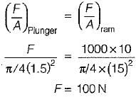
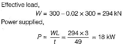
An accumulator has a ram of 250 mm in diameter. The effective stroke of the ram is 3 m and the total load on the ram is 300 kN. The frictional effects in the accumulator can be taken as 2% of the total load on the ram. What is the total power delivered by the accumulator when ram falls through its full stroke in 49 seconds?- a)10 kW
- b)13 kW
- c)15 kW
- d)18 kW
Correct answer is option 'D'. Can you explain this answer?
An accumulator has a ram of 250 mm in diameter. The effective stroke of the ram is 3 m and the total load on the ram is 300 kN. The frictional effects in the accumulator can be taken as 2% of the total load on the ram. What is the total power delivered by the accumulator when ram falls through its full stroke in 49 seconds?
a)
10 kW
b)
13 kW
c)
15 kW
d)
18 kW
|
|
Asha Basu answered |
As water flows through the runner of a reaction turbine, pressure acting on it would vary from- a)more than atmospheric pressure to vacuum
- b)less than atmospheric pressure to zero gauge pressure
- c)atmospheric pressure to more than atmospheric pressure
- d)atmospheric pressure to vacuum
Correct answer is option 'A'. Can you explain this answer?
As water flows through the runner of a reaction turbine, pressure acting on it would vary from
a)
more than atmospheric pressure to vacuum
b)
less than atmospheric pressure to zero gauge pressure
c)
atmospheric pressure to more than atmospheric pressure
d)
atmospheric pressure to vacuum
|
|
Anmol Menon answered |
At inlet of reaction turbine water is admitted with high pressure head (above atmospheric pressure) with some kinetic energy. The pressure head of water gradually decreases from inlet to exit. Finally water leaves the runner with low pressure and small kinetic energy to tail race. Quite often, the pressure head of the water at turbine exit fall below the ambient pressure. A draft tube attached to the exit of the turbine, working like a diffuser converts the remaining kinetic energy of water discharged by the runner into the pressure energy so that water is discharged to the tail race with a positive pressure head to avoid cavitation.
At the eye tip of a centrifugal impeller, blade velocity is 200 m/s. While the uniform velocity at the inlet is 150 m/s. If the sonic velocity is 300 m/s then the inlet mach number of the flow will be- a)0.75
- b)0.66
- c)0.90
- d)0.83
Correct answer is option 'B'. Can you explain this answer?
At the eye tip of a centrifugal impeller, blade velocity is 200 m/s. While the uniform velocity at the inlet is 150 m/s. If the sonic velocity is 300 m/s then the inlet mach number of the flow will be
a)
0.75
b)
0.66
c)
0.90
d)
0.83
|
|
Mrinalini Sharma answered |
The given problem deals with the flow velocities at the eye tip of a centrifugal impeller. We are given the blade velocity at the eye tip as 200 m/s, the uniform velocity at the inlet as 150 m/s, and the sonic velocity as 300 m/s. We need to find the inlet Mach number of the flow.
To solve this problem, we can use the equation for Mach number:
Mach number = Velocity / Sonic velocity
Let's calculate the inlet Mach number step by step:
1. Calculate the inlet velocity relative to the blade velocity:
Inlet relative velocity = Blade velocity - Inlet velocity
Inlet relative velocity = 200 m/s - 150 m/s
Inlet relative velocity = 50 m/s
2. Calculate the inlet Mach number:
Inlet Mach number = Inlet relative velocity / Sonic velocity
Inlet Mach number = 50 m/s / 300 m/s
Inlet Mach number ≈ 0.1667
Therefore, the inlet Mach number of the flow is approximately 0.1667.
Now let's compare the calculated Mach number with the given options:
a) 0.75
b) 0.66 (Correct Answer)
c) 0.90
d) 0.83
The calculated Mach number is less than all the given options. Therefore, the correct answer is option 'b' (0.66), as it is the closest value to the calculated Mach number.
In conclusion, the inlet Mach number of the flow is approximately 0.1667, and the correct answer is option 'b' (0.66).
In impulse turbine, the steam expands- a)in the nozzle
- b)in the blades
- c)partially in nozzle, partially in blades
- d)cannot say in which
Correct answer is option 'A'. Can you explain this answer?
In impulse turbine, the steam expands
a)
in the nozzle
b)
in the blades
c)
partially in nozzle, partially in blades
d)
cannot say in which
|
|
Ayush Chawla answered |
Impulse Turbine:
An impulse turbine is a type of steam turbine where the steam expands solely in the nozzle. It is commonly used in power generation plants to convert the kinetic energy of a high-velocity steam jet into mechanical energy.
Working Principle:
The working principle of an impulse turbine is based on the Newton's second law of motion, which states that the change in momentum of an object is equal to the force acting on it multiplied by the time during which the force is applied. In an impulse turbine, the steam is accelerated to a high velocity in the nozzle, and then directed onto the blades of the rotor.
Expansion in the Nozzle:
In an impulse turbine, the steam expands only in the nozzle. The nozzle is designed to provide a high-velocity steam jet by gradually increasing the cross-sectional area in the direction of flow. This causes the steam to undergo a controlled expansion, resulting in an increase in its velocity.
Velocity and Kinetic Energy Conversion:
As the steam expands in the nozzle, its velocity increases. This is due to the conservation of mass principle, which states that the mass flow rate of a fluid remains constant throughout a flow system. Therefore, as the cross-sectional area of the nozzle increases, the velocity of the steam increases to maintain the constant mass flow rate.
The high-velocity steam jet then impacts the blades of the rotor, causing a change in momentum. This change in momentum results in a force being exerted on the blades, which causes them to rotate. As the blades rotate, they convert the kinetic energy of the steam into mechanical energy.
Blades:
The blades in an impulse turbine are designed to efficiently capture the kinetic energy of the steam and convert it into rotational motion. They are typically curved or shaped in a way that allows the steam to flow smoothly over them, minimizing any losses due to friction or turbulence.
Nozzle Design:
The design of the nozzle is crucial in an impulse turbine as it determines the expansion of the steam and the resulting velocity. The nozzle should be carefully designed to achieve the desired steam velocity and ensure that the steam expands completely within the nozzle before it impacts the blades.
Conclusion:
In an impulse turbine, the steam expands only in the nozzle. The nozzle is designed to provide a high-velocity steam jet, which impacts the blades and causes them to rotate. The expansion of the steam in the nozzle and its subsequent impact on the blades result in the conversion of kinetic energy into mechanical energy, making impulse turbines an efficient choice for power generation.
Consider the following statements:
1. The speed of rotation of the moving elements of gas turbines is much higher than of steam turbine.
2. Gas turbine plants are heavier and larger in size than steam power plants.
3. Gas turbines require cooling water for their operations.
4. Any kind of fuel can be used with gas turbines.
Which of the statements given above are correct?- a)1 and 2
- b)1 and 3
- c)1 and 4
- d)3 and 4
Correct answer is option 'C'. Can you explain this answer?
Consider the following statements:
1. The speed of rotation of the moving elements of gas turbines is much higher than of steam turbine.
2. Gas turbine plants are heavier and larger in size than steam power plants.
3. Gas turbines require cooling water for their operations.
4. Any kind of fuel can be used with gas turbines.
Which of the statements given above are correct?
a)
1 and 2
b)
1 and 3
c)
1 and 4
d)
3 and 4
|
|
Abhay Banerjee answered |
Statement 1: The speed of rotation of the moving elements of gas turbines is much higher than of steam turbine.
This statement is correct. Gas turbines typically operate at much higher rotational speeds than steam turbines. Gas turbines can reach speeds of up to 30,000 revolutions per minute (RPM), while steam turbines usually operate at speeds around 3,600 RPM. The high rotational speed of gas turbines is necessary to achieve high power output and efficiency.
Statement 2: Gas turbine plants are heavier and larger in size than steam power plants.
This statement is incorrect. Gas turbine plants are generally smaller and lighter than steam power plants. This is because gas turbines have a higher power-to-weight ratio compared to steam turbines. Gas turbine plants also have a simpler design and fewer components, which contributes to their compact size and lower weight. Steam power plants, on the other hand, require large boilers, condensers, and other equipment, making them bulkier and heavier.
Statement 3: Gas turbines require cooling water for their operations.
This statement is incorrect. Gas turbines do not require cooling water for their operations. They are air-cooled machines, meaning that they use ambient air to cool down their components. Air is drawn into the turbine and used to cool the hot gases and the turbine blades. This eliminates the need for a separate cooling water system, simplifying the turbine plant design and reducing water consumption.
Statement 4: Any kind of fuel can be used with gas turbines.
This statement is correct. Gas turbines are versatile machines that can operate on a wide range of fuels. They can burn natural gas, diesel, kerosene, biofuels, and even synthetic fuels. The flexibility in fuel choice makes gas turbines suitable for various applications, including power generation, aviation, and industrial processes. The combustion process in gas turbines is highly efficient, resulting in lower emissions and better fuel utilization.
In conclusion, the correct statements are 1 and 4. The speed of rotation of gas turbines is indeed higher than that of steam turbines, and gas turbines can utilize a wide range of fuels. However, gas turbine plants are generally smaller and lighter than steam power plants, and they do not require cooling water for their operations.
Consider the following parameters:
1. Impeller diameter
2. Fluid density
3. Speed
4. Type of casingHead developed by a certrifugal pump depends on- a)1 and 3
- b)1, 2 and 3
- c)1, 3 and 4
- d)2 and 3
Correct answer is option 'A'. Can you explain this answer?
Consider the following parameters:
1. Impeller diameter
2. Fluid density
3. Speed
4. Type of casing
1. Impeller diameter
2. Fluid density
3. Speed
4. Type of casing
Head developed by a certrifugal pump depends on
a)
1 and 3
b)
1, 2 and 3
c)
1, 3 and 4
d)
2 and 3
|
|
Jhanvi Datta answered |
Impeller diameter and speed are the key parameters
Head developed by a centrifugal pump depends primarily on the impeller diameter and the speed of rotation.
Impeller diameter
- The impeller diameter plays a crucial role in determining the head developed because it directly affects the velocity and pressure of the fluid being pumped.
- A larger impeller diameter typically results in higher head development due to increased fluid flow and pressure.
Speed
- The speed of rotation of the impeller also significantly impacts the head developed by a centrifugal pump.
- Higher speeds generally lead to greater head development as the impeller can impart more energy to the fluid.
Therefore, the correct answer is option 'A' - Head developed by a centrifugal pump depends on impeller diameter and speed. Other parameters such as fluid density and type of casing may have some influence on the performance of the pump, but they are not as directly related to head development as impeller diameter and speed.
Consider the following statements:
The efficiency of the vapour power Rankine cycle can increased by
1. Increasing the temperature of the working fluid at which heat is added
2. Increasing the pressure of the working fluid at which heat is added
3. Decreasing the temperature of the working fluid at which heat is reject
Q. Which of these statements is/are correct?- a)2 and 3
- b)1 only
- c)1 and 2
- d)1, 2 and 3
Correct answer is option 'D'. Can you explain this answer?
Consider the following statements:
The efficiency of the vapour power Rankine cycle can increased by
1. Increasing the temperature of the working fluid at which heat is added
2. Increasing the pressure of the working fluid at which heat is added
3. Decreasing the temperature of the working fluid at which heat is reject
Q. Which of these statements is/are correct?
a)
2 and 3
b)
1 only
c)
1 and 2
d)
1, 2 and 3
|
|
Kavya Mehta answered |
Where T2 is the temperature of the rejection and T1, is the temperature of heat added. Efficiency increases when T2 decreases and T1, increases. An increases in the pressure of working fluid increases the mean temperature of heat addition and hence increases the cycle efficiency.
The energy released during the fission of one atom of U-235 in MeV is about- a)100
- b)200
- c)300
- d)400
Correct answer is option 'B'. Can you explain this answer?
The energy released during the fission of one atom of U-235 in MeV is about
a)
100
b)
200
c)
300
d)
400
|
|
Pankaj Joshi answered |
Explanation:
Fission of Uranium-235:
- Uranium-235 is a fissile isotope of uranium, meaning it can undergo nuclear fission.
- Nuclear fission is a process in which the nucleus of an atom splits into two smaller nuclei, releasing a large amount of energy in the process.
Energy Released during Fission:
- The energy released during the fission of one atom of U-235 can be calculated using the famous equation E=mc², where E represents energy, m represents mass, and c represents the speed of light.
- The difference in mass between the original uranium atom and the two resulting nuclei, known as the mass defect, is converted into energy according to Einstein's equation.
- In the case of U-235, the average mass of the two resulting nuclei is slightly less than the mass of the original uranium atom.
- This mass difference is converted into energy according to the equation E=mc².
- The energy released during the fission of one atom of U-235 is approximately 200 MeV (million electron volts).
Answer:
- The correct answer is option 'B' which states that the energy released during the fission of one atom of U-235 is about 200 MeV.
Which of the following method is/are adopted to bring down the speed of an impulse turbine to practical limits?
1. Use of flywheels
2. Use of governor
3. Compounding
4. Increasing the loadSelect the correct answer using the code given below:- a)1 and 2
- b)2 only
- c)3 only
- d)1, 2, 3 and 4
Correct answer is option 'C'. Can you explain this answer?
Which of the following method is/are adopted to bring down the speed of an impulse turbine to practical limits?
1. Use of flywheels
2. Use of governor
3. Compounding
4. Increasing the load
1. Use of flywheels
2. Use of governor
3. Compounding
4. Increasing the load
Select the correct answer using the code given below:
a)
1 and 2
b)
2 only
c)
3 only
d)
1, 2, 3 and 4
|
|
Pallabi Tiwari answered |
The correct answer is option C: 3 only.
Impulse turbines are commonly used in hydroelectric power plants to convert the kinetic energy of water into mechanical energy. These turbines operate at high speeds due to the high velocity of water flowing through them. However, in practical applications, it is necessary to bring down the speed of the turbine to ensure safe and efficient operation. Several methods are adopted to achieve this:
1. Compounding:
Compounding is a technique used to reduce the speed of an impulse turbine. It involves dividing the turbine into multiple stages, each with its own set of nozzles and blades. The high-speed jet of water is directed onto the first set of nozzles and blades, where it imparts a partial amount of its kinetic energy. The remaining energy is then directed onto the next set of nozzles and blades, and so on. This process is repeated in multiple stages, gradually reducing the speed of the turbine. Compounding is an effective method to bring down the speed of an impulse turbine while maintaining high efficiency.
2. Use of Governor:
A governor is a device used to regulate the speed of a turbine. It consists of a set of rotating weights connected to the turbine shaft. As the speed of the turbine increases, the centrifugal force acting on the weights increases. This force causes the weights to move outward, which in turn actuates a mechanism that reduces the flow of water to the turbine, thereby reducing its speed. Conversely, when the speed decreases, the weights move inward, allowing more water to flow into the turbine and increase its speed. Governors are commonly used in conjunction with impulse turbines to maintain a constant speed and prevent overspeeding.
3. Increasing the Load:
Increasing the load on the turbine is another method to bring down its speed. By connecting more devices or generators to the turbine shaft, the torque required to drive these devices increases. As a result, the turbine slows down to match the increased load. This method is commonly used in power plants where the electricity demand varies, allowing the turbine to adjust its speed according to the load.
In conclusion, the methods adopted to bring down the speed of an impulse turbine to practical limits include compounding, the use of a governor, and increasing the load. These methods are essential to ensure safe and efficient operation of the turbine in various applications.
Maximum impulse will be developed in hydraulic ram when- a)waste valve closes suddenly
- b)supply pipe is long
- c)supply pipe is short
- d)supply pipe has critical diameter
Correct answer is option 'A'. Can you explain this answer?
Maximum impulse will be developed in hydraulic ram when
a)
waste valve closes suddenly
b)
supply pipe is long
c)
supply pipe is short
d)
supply pipe has critical diameter
|
|
Siddharth Menon answered |
Impulse is created in very short duration of time. The flow of water is maximum in the supply pipe just before the closure of the waste valve.
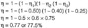
For a mercury-steam sulphur-dioxide cycle, the heat rejected in the mercury cycle is given to the steam cycle and the heat rejected in the steam cycle is utilized in SO2 cycle. If the efficiencies of the mercury, steam and SO2 cycle 0.5, 0.4 and 0.25 respectively, then overall efficiency of the composite cycle is- a)77.5%
- b)5%
- c)95%
- d)22.5%
Correct answer is option 'A'. Can you explain this answer?
For a mercury-steam sulphur-dioxide cycle, the heat rejected in the mercury cycle is given to the steam cycle and the heat rejected in the steam cycle is utilized in SO2 cycle. If the efficiencies of the mercury, steam and SO2 cycle 0.5, 0.4 and 0.25 respectively, then overall efficiency of the composite cycle is
a)
77.5%
b)
5%
c)
95%
d)
22.5%
|
|
Muskaan Sen answered |
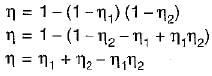
For 3 cycles coupled in series the overall efficiency of the combined cycle is given by
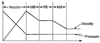
What changes occur in pressure and velocity when steam flows through the second row of moving blades of a velocity compounded impulse turbine?- a)velocity decreases and pressure remains constant
- b)pressure decreases and velocity remains constant
- c)both velocity and pressure remains constant
- d)both velocity and pressure decrease
Correct answer is option 'A'. Can you explain this answer?
What changes occur in pressure and velocity when steam flows through the second row of moving blades of a velocity compounded impulse turbine?
a)
velocity decreases and pressure remains constant
b)
pressure decreases and velocity remains constant
c)
both velocity and pressure remains constant
d)
both velocity and pressure decrease
|
|
Shail Rane answered |
For a single stage impulse turbine with nozzle angle 15°, rotor diameter 2 m and speed 3000 rpm, the optimum velocity of steam in m/s is:
[Take cos15° = 0.966, sin15° = 0.258]- a)550
- b)600
- c)650
- d)700
Correct answer is option 'C'. Can you explain this answer?
For a single stage impulse turbine with nozzle angle 15°, rotor diameter 2 m and speed 3000 rpm, the optimum velocity of steam in m/s is:
[Take cos15° = 0.966, sin15° = 0.258]
[Take cos15° = 0.966, sin15° = 0.258]
a)
550
b)
600
c)
650
d)
700
|
|
Divya Banerjee answered |
The nozzle angle in a single-stage impulse turbine is typically set at 20-30 degrees. This angle is important as it determines the direction and velocity of the steam as it enters the turbine blades. A nozzle angle of 15 degrees would result in a less efficient turbine operation as the steam flow would not be optimally directed towards the blades.
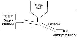
Surge tank is used in pipe line- a)to reduce frictional loss in pipe
- b)to ensure uniform flow in pipe
- c)to relieve the pressure due to water hammer
- d)to reduce cavitation
Correct answer is option 'C'. Can you explain this answer?
Surge tank is used in pipe line
a)
to reduce frictional loss in pipe
b)
to ensure uniform flow in pipe
c)
to relieve the pressure due to water hammer
d)
to reduce cavitation
|
|
Nishanth Banerjee answered |
Rapid velocity fluctuations occur in pipe line during
1. Sudden opening and closing of valves
2. Start and shut down of a turbine or closure of wicket gates during speed regulation of a turbine.
Due to rapid velocity fluctuations, large magnitude pressure transients are set-up and these excessive pressure may lead to bursting of pipe this phenomenon is known as water hammer. Some arrangement needs to be made to convert the rapid velocity fluctuations into slow velocity fluctuations and for this surge tank is provided just upstream of the power unit in a hydroelectric plant.
Chapter doubts & questions for Power Plant Engineering - Topicwise Question Bank for Mechanical Engineering 2025 is part of Mechanical Engineering exam preparation. The chapters have been prepared according to the Mechanical Engineering exam syllabus. The Chapter doubts & questions, notes, tests & MCQs are made for Mechanical Engineering 2025 Exam. Find important definitions, questions, notes, meanings, examples, exercises, MCQs and online tests here.
Chapter doubts & questions of Power Plant Engineering - Topicwise Question Bank for Mechanical Engineering in English & Hindi are available as part of Mechanical Engineering exam.
Download more important topics, notes, lectures and mock test series for Mechanical Engineering Exam by signing up for free.
Topicwise Question Bank for Mechanical Engineering
45 videos|314 tests
|
|
© EduRev
|
Education Revolution
|


|


Signup to see your scores
go up within 7 days!
Access 1000+ FREE Docs, Videos and Tests
Takes less than 10 seconds to signup